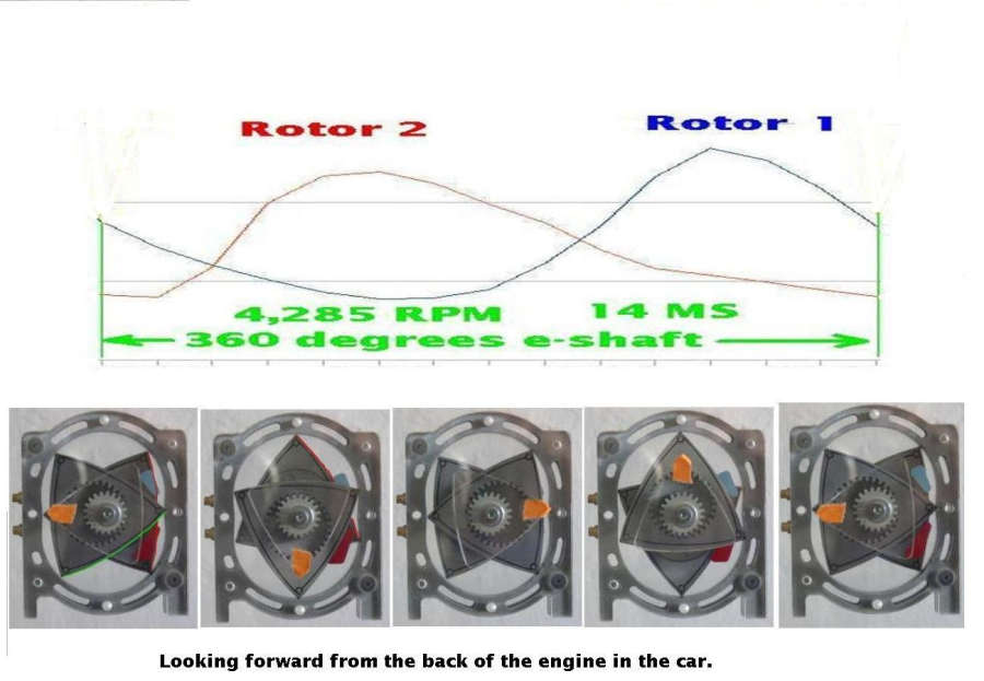
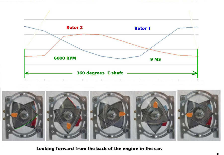
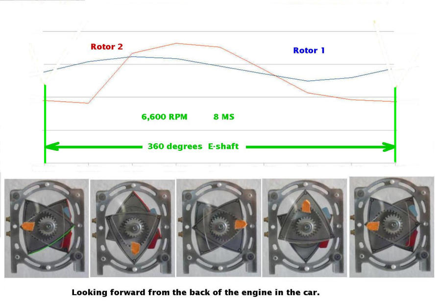
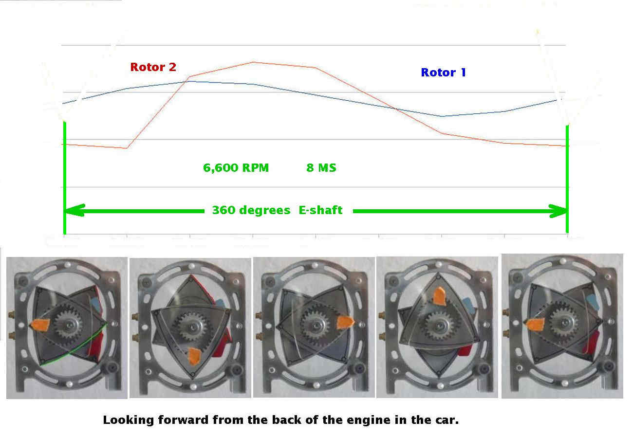
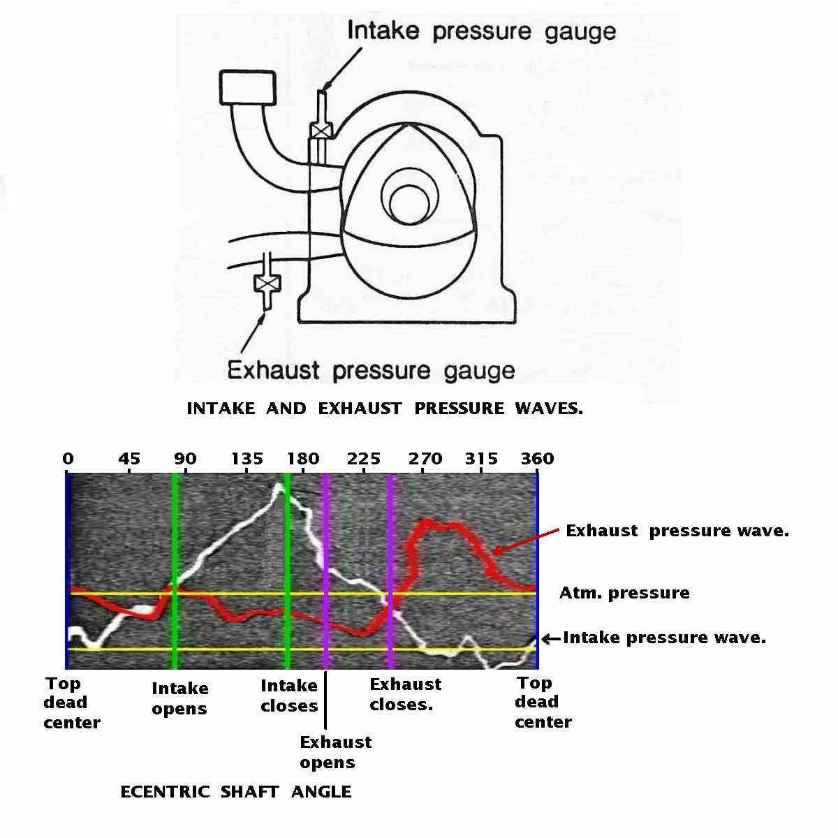
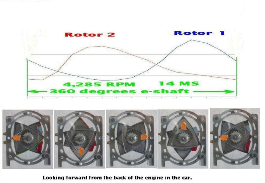
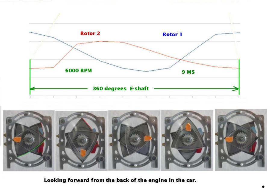
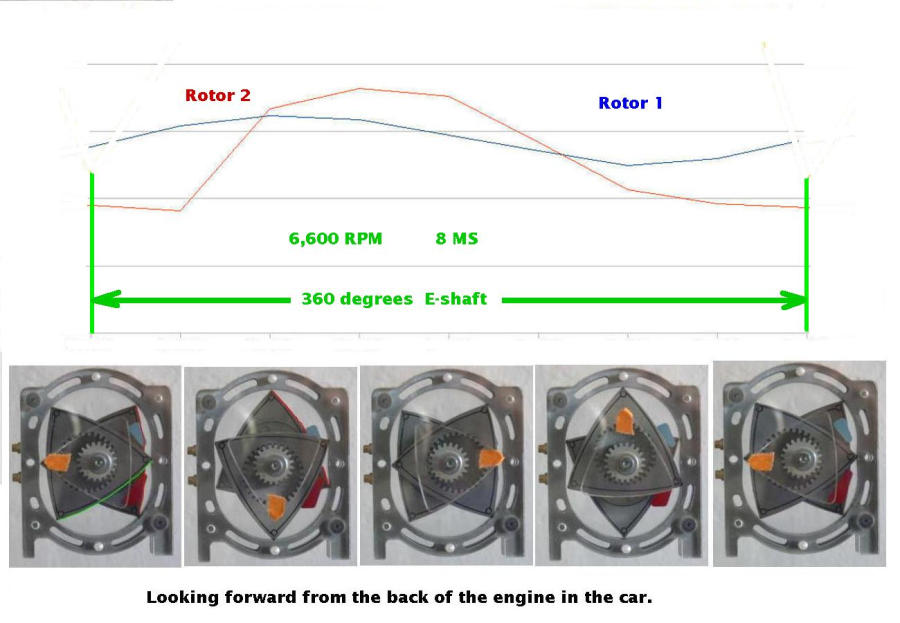
I think Jeff (jeff.doddridge@gmail.com) cut these down for Mazdatrix.
   It does away with the round oil seals which I suspect we don't need.
   The oil seals have unavoidable friction which in theory burns slightly
 more
   fuel.

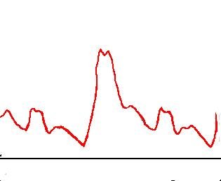
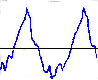
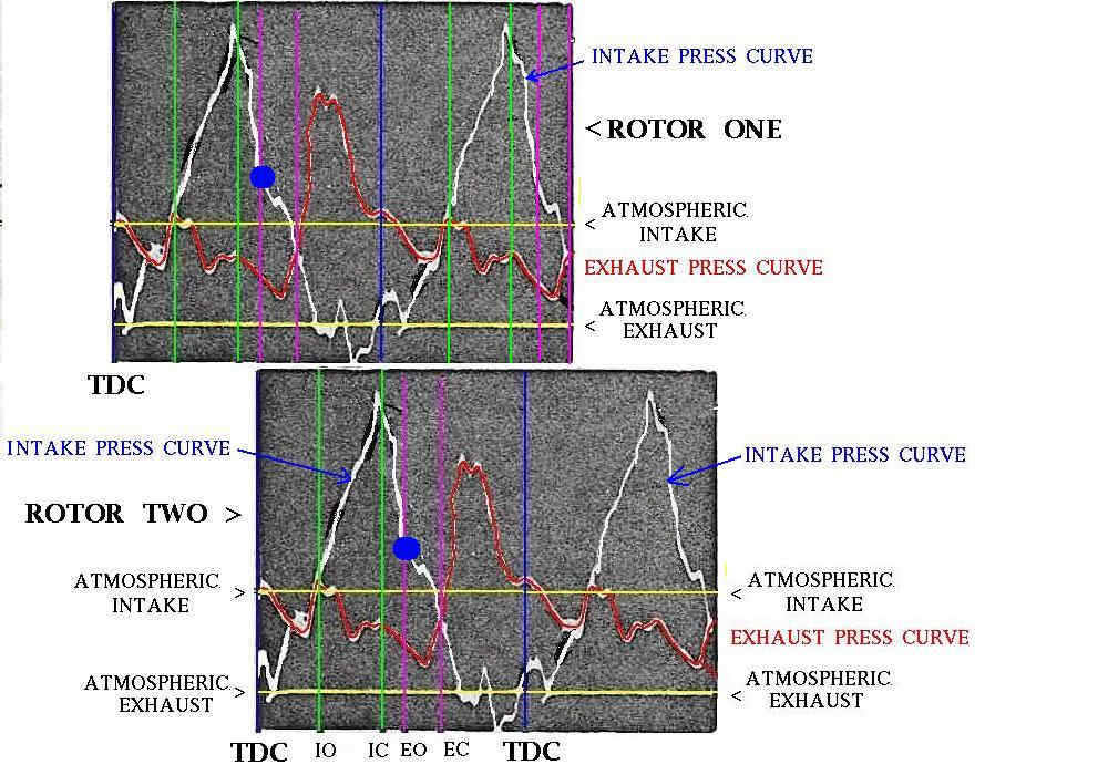
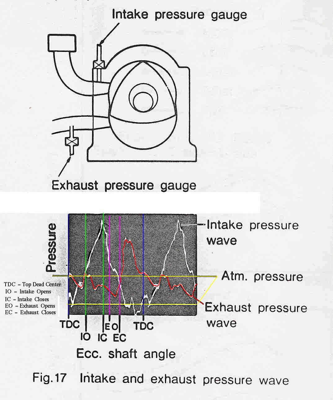
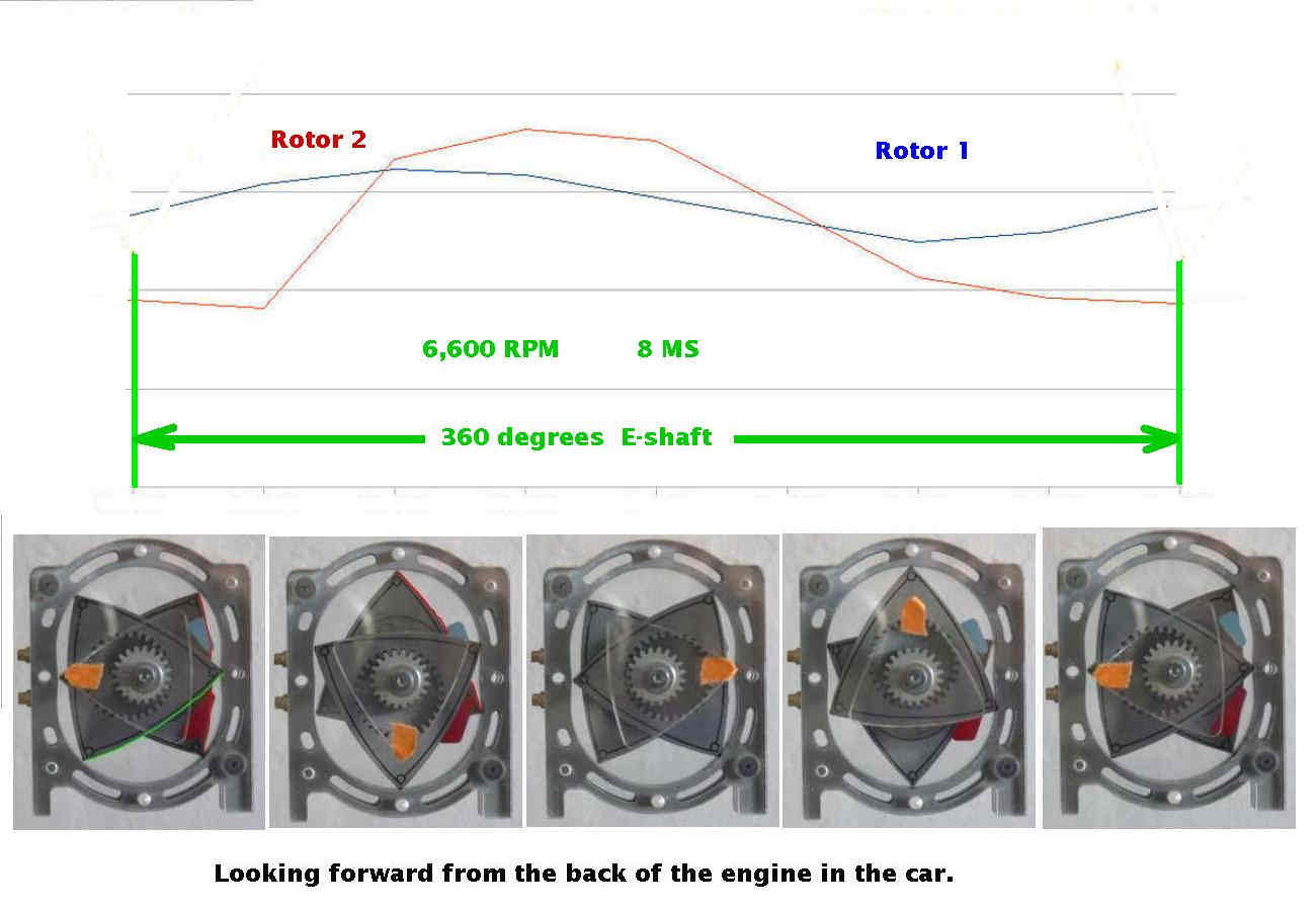
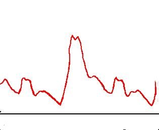
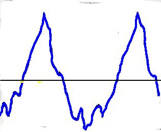
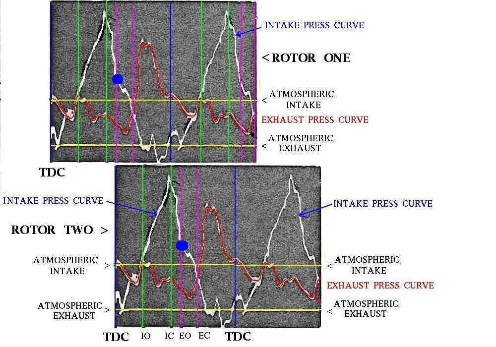
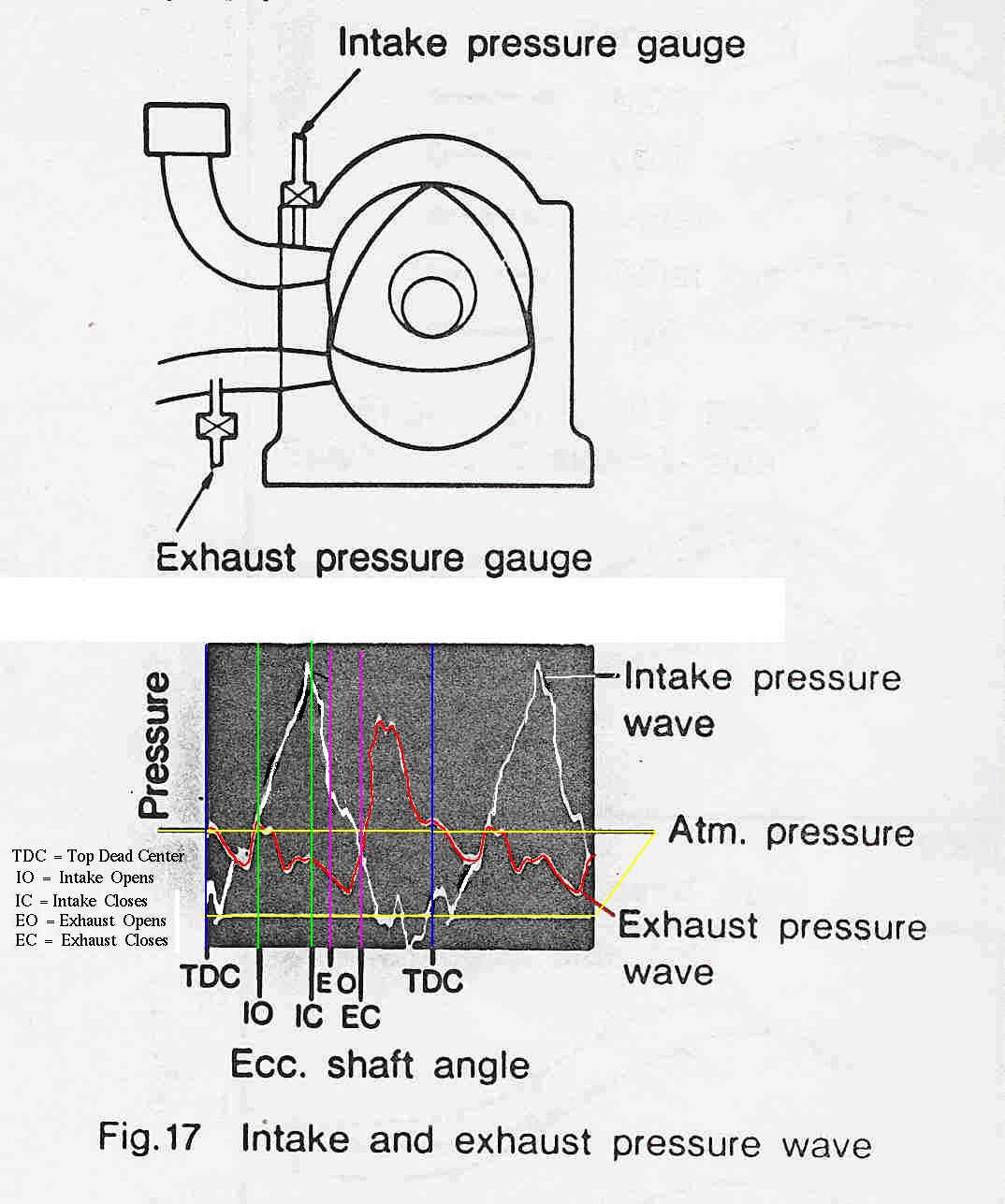
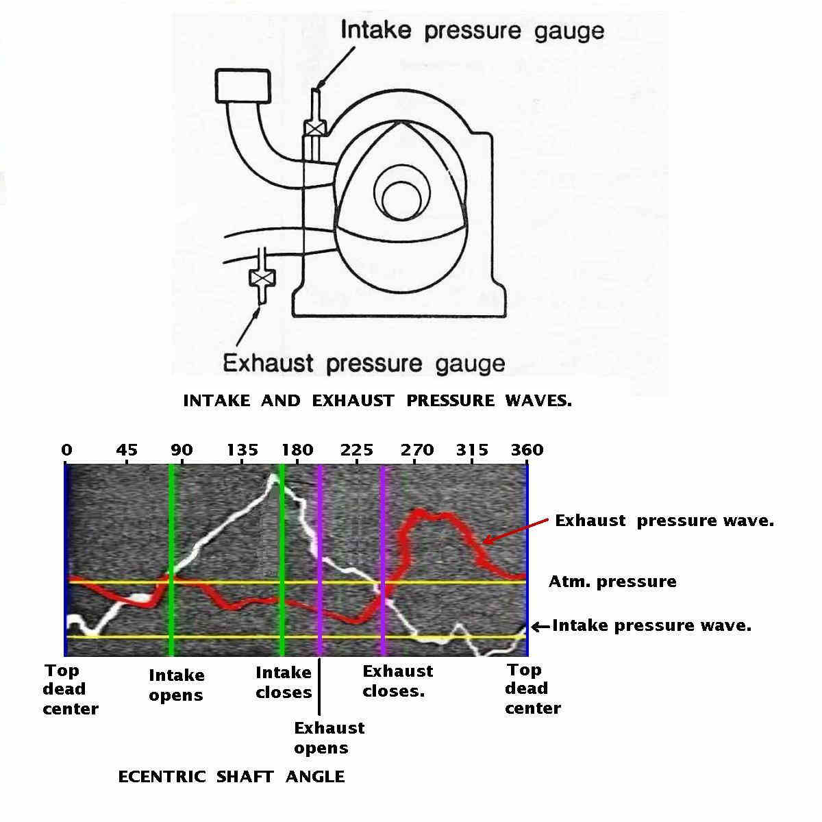
   My guess, based on these enclosed charts, is a 33% reduction in rotary
   engine friction. The engine will generate more power at the same RPM as
 well.

   Furthermore the side seals will get more oil for possibly lower side
 housing
   wear.

   It also cuts the weight of rotors so the counter weights are slightly
   lighter and the load on the rotor bearings is reduced at any given RPM.

   My Mazda Cosmo had melted oil seal O-rings and I drove it for years.
   It smoked like a radial engine when you started it up but then it stopped
   after a few seconds. I never noticed higher oil consumption.

   Mazda mentioned this when they were talking about the first rotary engine
 they
   built. It ran fine but they had to add the oil seals to solve the start
 up smoke
   problem.

   I think they will work fine in a p-port aircraft or racing car engine.

   Sorry about the cell phone pictures. I forget my good camera when I
 visited
   Mazdatrix.

   Paul Lamar

   Paul,
   Best idea I have seen in a while. as long as the side seal gaps are done
   very well, this should work fine. I once worked a an engine that a school
   had rebuilt and the oil seals were installed upside down. Smoked like a
 navy
   smoke layer.... but the side seal gaps were big as well. I like the
 increase
   in corner seal oiling.... I think I might have to build one of these to
   try....
   Larry

   Great minds.........:)

   Paul Lamar

   Paul,
   for anyone doing this, make sure you radius off all the sharp corners left
   by the end mill...... unless you like cracks
   Larry

   I just had another idea. The amount of oil retained in the rotor after
 the engine
   stops depends of the size of the large oil drain back oil in the center
 housing. This
   oil will leak down and get to the bottom of the engine to create smoke on
 start.
   Making the large drain back hole even larger will reduce the quantity. It
 will also
   cut a bit of weight out of the center housing.

   Another possibility is a tiny .032" dia. drain hole drilled in the bottom
 of the
   rotor housings letting the accumulated oil slowly drain back to the oil
 pan.

   This may eliminate the smoke on start up.

   Paul Lamar

     Hi  Paul,
                      You guys are always coming up with something new
 for rotaries, as I have said before I think that if even a fraction of
 the effort that has been put into
    piston engines into rotaries the rotary would not be on the bottom of
 "joe blow"  wanna list. The big factories do not have all the answers.
                    John Burey.

 Paul,   I would be concerned about opening up the size of the center
 housing where the E-shaft passes thru.  The shaft and rotors operate in a
 semi-flooded condition to remove heat from the rotor. Enlarging the hole
 would reduce the oil   volume in this area. Also the  "dogleg"  in the
 E-shaft appears to me to pump any oil that gets to the center housing back
 to the pan and with a lower oil level foaming of the oil could be a
 possibility. The removing of this much surface area would also reduce the
 amount of heat that can travel thru the center housing to the water
 jacket.  A small  (.090?) hole at the bottom of the red line in  the
 attachment would vent to an area of nearly equal pressure and lower the
 retained shut down oil level slightly.

         It would seem that the real issue is oil that finds it's way past
 the rotor side combustion seals which is an area lower than the drain.  I
 see in the other attachment an idea to vent the bottom of the rotor
 housing. This area is under constant combustion pressure from the
 continuous expansion strokes and would vent into the oil system
 both exhaust gasses and some particulate residues.  This could however be
 made to work. Rather than going thru the water passage it would seem better
 to go through the clearance between the tension bolt and it's hole which is
 relatively large in the rotor housings, moreso than the side housings which
 are drilled holes. These holes run between the water jacket seals and are
 therefore not intended to be sealed from coolant, however "O" rings similar
 to those around the hollow dowels could isolate a bolt hole.  The oil port
 would need to be sealed during operation but open at shut down. I might
 suggest a plunger ported to be closed by the exhaust pressure  or by engine
 oil pressure on a differential area spool as used in a balanced pressure
 hydraulic relief valve. The large area side overcomes the smaller area side
 because they see the same pressure..

         When we get done chewing on this bone how about a thread dealing
 with exhaust headers.  So far it seems that 32" long is the only advice.
 How about diameter and is the diameter constant or increasing slightly.
 Also I read something about  an inverted cone a few inches from the end of
 the header which reflects a sound wave back up the pipe to cancel the
 outgoing wave sound. Apparently having it at a distance still allows some
 exhaust scavenging because the pressure wave reflects back from the end of
 the pipe similar to the intake runner at 18" length.      With parts from
 Jeff  and RWS we can get the engine bolted to the airframe  with a prop,
 the EFI and ignition.  We now have a handle on the cooling thanks to your
 book so might it be time to tinker with the exhaust side a little.

 george grimes

 Due to the complex orbiting motion of the rotor the cooling oil, what there
 is of it,
 stays out near the apex seal slots. It is less oil than most people think.

 There is not going to be a lot of exhaust gases coming through .032 dia.
 hole.
 The hole is drilled in a vertical rib in the bottom of the rotor housing. It
 does not
 intersect cooling passages.

 Paul Lamar


 Did some playing with a 12A rotor to see what impact it could have on my
 single rotor
 work.
 The impact would be significant, if it works.
 The rotor in the picture weighs 3,500g versus 4357 in original
 configuration. Running
 this weight through balancing analysis shows less balancing moment required
 on the
 balance weight than on a two rotor. This alone is worth pursuing this for
 the single
 rotor.
 Machining the rotor on the CNC is a no-brainer.
 Who came up with that idea anyway?  Probably the most significant one in a
 long time.
 The only technical issue still open is demonstrating rotor balancing. If
 MazdaTrix
 can do it, I would put that rotor in my test engine and see what happens.
 Anyway, thanks to the guy who came up with this.

 Richard Sohn
 N2071U

 http://www.fairpoint.net/~res12/home.html


 It was Jeff as far as I know.

 Paul Lamar

 This last jpg is of a Wankel AG rotor. No oil seals.

 Paul Lamar


 Man, the more I read about the rotary, the more I like it.  Seems VERY
 durable as well.

 Barron


  Hi  Paul,
                     I have a book called "Scientific design of exhaust
and intake systems", written by Phillip H. Smith, published by
G.T.Fou;is & Co. Ltd. London. I have had my copy about 40 years, (I
notice it says inside the cover "Not to be sold in the USA", )???,
Cannot have those jolly yanks finding out what we are doing can we?
                    It is very easy to follow and shows how to take
advantage of and to reduce the down sides to exhaust and intake pulses,
I also have a book called "Two stroke tuners handbook", by Gordon
Jennings, published by HP books in Tucson, Arizona. HP books: 41-ISBN
0-912656-41-7. It also details the exhaust length ect., I would think
that probably a book dealing with two stroke engines, ie. without
exhaust valves would probably be more relevant to the exhaust of a
rotary, Gordon talks about exhaust temperature of around 1200degrees??
and with a wave speed of around 1700 feet per second!! I think you said
Paul that the exhaust temperature was about 1600/1800deg. F. ?
                    John Burey

I have the 1971 third edition.
I am not sure how one can apply the data to a rotary. Unlike a piston engine the
ports are never really closed. One gets pressure variations but some ports in a 4
cycle are completely closed for a whole rev. Your right. The rotary is more like a
two cycle in this regard.... or a gas turbine in the case of a p-port.

Yes on the exhaust temperature for a rotary. A 2 cyle piston engine has a certain
amount of fresh charge in the exhaust. It is called scavenge ratio. That cools it
compared to a 4 cycle rotary.


Paul Lamar

--
The Rotary Engine News Letter. Powered by Linux.
ACRE NL web site. http://www.rotaryeng.net
You Tube key word PaulLamar2
Copyright 1998-2012 All world wide rights reserved.