This looks like a real simple way of using megasquirts on rotaries and you
 have
 redundancy. The engine will run on one rotor. It solves a lot of problems
 using just
 one Megasquirt on a rotary.

 I has the advantage of using a notebook computer with a USB connector to
 tune and
 save injector tables to share with other people merely by emailing them.
 Megatune is very sophisticated and easy to use tuning software that runs
 on a notebook.

 IMHO this is a great idea.

 Paul Lamar

 -----------------------------------------------------------
 Using MegaSquirt ‘out of the .box’

 www.not2fast.com/megasquirt/doc/rotary_injection.doc

 MegaSquirt introduction.
 The MegaSquirt was design by Bruce Bowling and Al Grippo to be a simple
 and cheap
 batch fire fuel injection system. Been around for years.

 There are 2 injector driver outputs on the MegaSquirt, running off the PWM
 channels
 of the MCU. This allows both saturated and peak and hold injectors to be
 used on the
 same hardware: very clever. This allows 2 different injection events to
 occur in
 parallel, which suits our purposes very nicely.


 Specific needs of Rotary engines.

 The rotary engine, due to the rotor layout has a few key differences with
 a
 reciprocating engine. Many of these work in our favor. And remember, the
 otto cycle
 is the otto cycle:

 There are 2 rotors, spaced 180° apart. EFI.

 Build 2 MegaSquirts.

 Fit a pair of hall effect sensors one at 22 degrees BTDC and  one 180°
 later (top and
 bottom) Hook one MegaSquirt to the top sensor and one to the bottom.
 Burn in injector staging code if required.

 Ignition.
 The ignition pulse on 1 rotor corresponds to 22° BTDC on the inlet cycle
 of the other
 rotor, give or take the amount of advance being used. Very handy.

 Use 2 MSD capacitor discharge units per rotor. One per plug. This is what
 the racers
 do and is it very simple and straight forward. Each Hall Effect sensor
 fires two MSD
 units 22 degree BTDC.

 Injection.
 Around 220-280° is available for injection. In a reciprocating engine, you
 can ‘puddle’ fuel on the inlet port to increase the injection time. In a
 rotary there
 is little time for this before the next inlet cycle starts. This forces
 relatively
 large injectors to be used, with staged injection being a
 useful method of getting high max flow rates and a good dynamic range. For
 example,
 at 8000 RPM 1 revolution is 7.5ms, giving around 6ms for injection.

 In terms of injector strategies there are a couple in general use
 The best for our use here is 2 injectors in each runner.

 The code mods are very simple, if needed at all
 You get the full 6 ms for injection at high RPM
 2 MegaSquirts are needed so adding a full $100 to the costs
 Tuning will be a little more tricky as you have to set each parameter
 twice

 ----------------------------------------------------------------


 I had an idea of using 3 megasquirts that fed a logic box that compares
 the outputs
 and forwards the one that at least 2 ms boxes agree on. Not sure if it's
 really
 feasible since that would induce some lag in the outputs.
 Joshua

 ---------------------------------------------------------------------


 SymTech Labs' coolant temperature sensor is a standard GM CLT sensor
 capable of
 interfacing with all MegaSquirt ECU's. It features 3/8" NPT threads and
 can also be
 used as an intake air temperature sensor (IAT/MAT). Each unit is shipped
 with a 6"
 pigtail for easy installation.

 Intake Air Temp/Manifold Air Temp

 The big question that I have is there seems to be conflicting info. Often
 they talk
 about a MAP sensor but this block diagram does not show it. A Manifold Air
 Pressure
 sensor (MAP) can be used to control the amount of fuel injected just like
 an O2
 sensor. That is what Tracy does.

 Any type of feed back from an O2 sensor will not work as 100LL is death to
 O2 sensors.

 The MS flow chart shows a read of the MAP but the schematic shows no
 connection to a
 MAP sensor.

 Can anybody help me out on this? Is the sensor on the mother board? Where
 is it
 connected?

 BTW The megasquirt has the built in capability to send engine parameters
 back to the
 notebook in real time for use as an EFIS. The notebook software is already
 available
 to display these engine parms in real time. This is a real cheap EFIS.

 Paul Lamar

 Separate Megasquirts for each rotor is a great idea as long as there is no
 danger of fire or explosion if the ignition for one rotor fails but the
 fuel in-
 jector continues, and unburned fuel air mixture continues out into the hot
 rotary exhaust environment.  Perhaps an electronic switch can be in-
 corporated into the Megasquirt circuitry that allows the fuel injector to
 fire
 only after a recent ignition signal--"recent" as established from voltage
 remaining in a capacitor which is otherwise charged from ignition
 activity.

 I am very interested in this one-megasq-per-rotor approach and would
 appreciate if anyone has any ideas.  Thanks.

 Gene Kahn

Gene,
Had a computer re-installed in my 86 RX7 and an injector pin got crossed
over into a ground. The injector went to a steady on state. Was totally
undriveable, smoked like all get out but didn't seem to pose any fire risk.

John

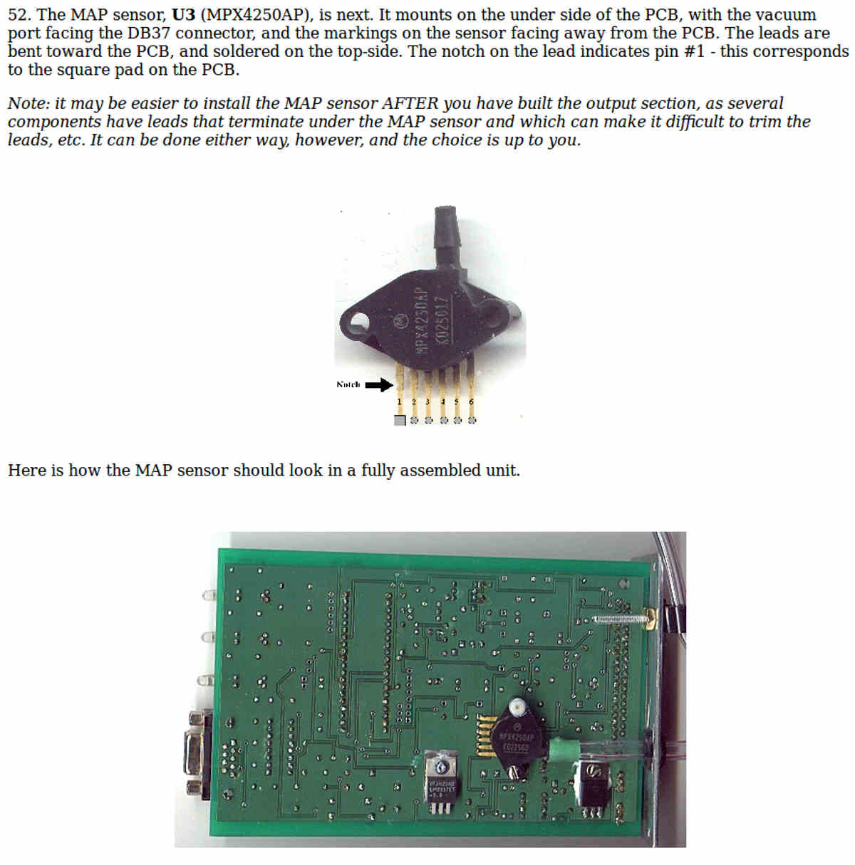
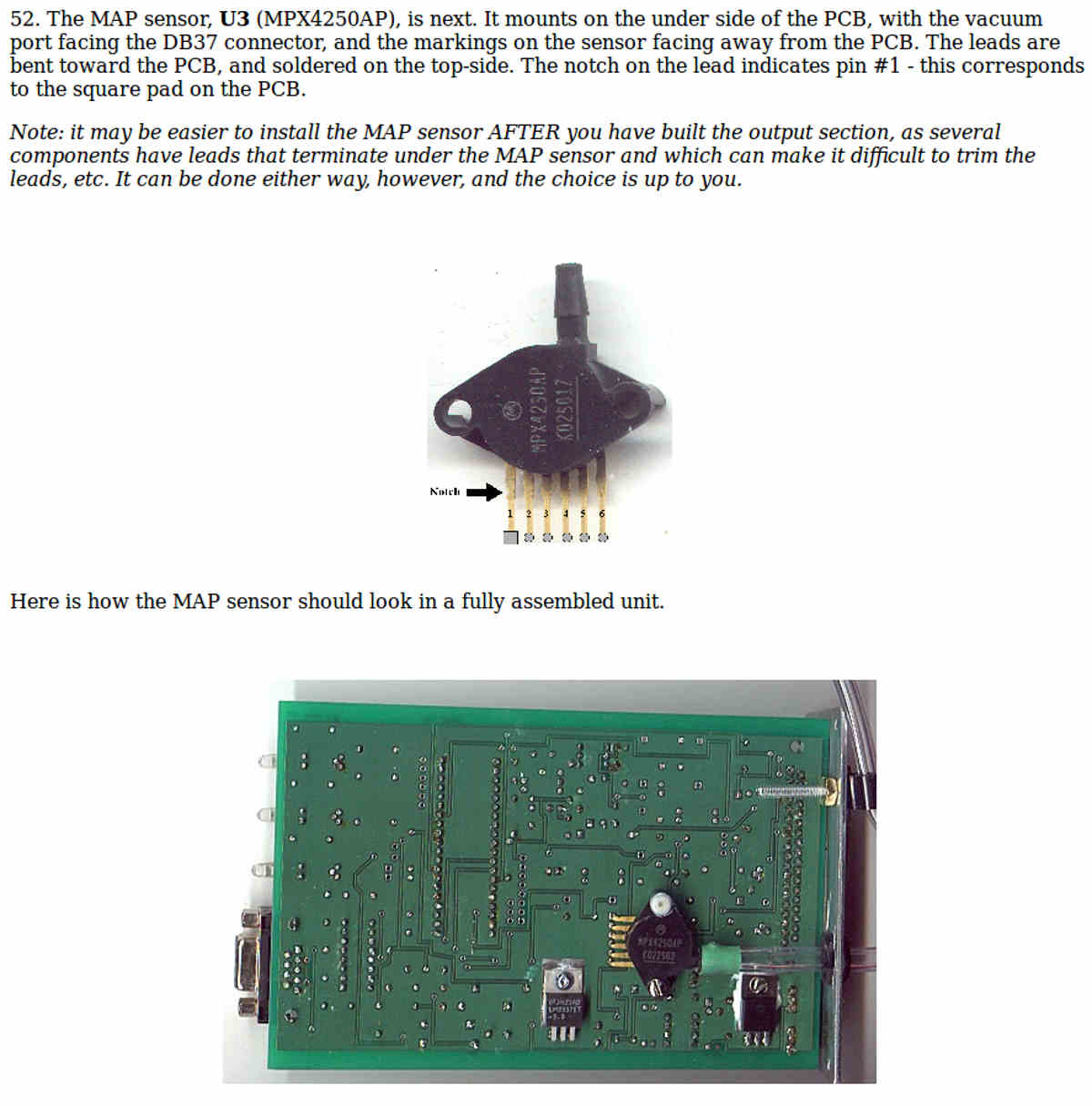
Finally found the MAP sensor. It is mounted on the back side of the board.
Tracy uses the same sensor.

There are dozens of files in MS on the internet. I don't know how anybody is expected
to sort all this stuff out. If I did not have extensive experience in this biz I
would be lost.

http://www.rotaryeng.net/IEEE-road-test-sys.pdf


Paul Lamar


--
The Rotary Engine News Letter. Powered by Linux.
ACRE NL web site. http://www.rotaryeng.net
You Tube key word PaulLamar2
Copyright 1998-2012 All world wide rights reserved.