I've always been an indifferent programmer, and I have 0 experience with 68 asm. I
  could probably muddle through it and end up with something that works though. Are you
  looking for someone to make modifications to the MS source?

  I've been thinking, and it may make more sense to use something like the TPS input.
  MS has a neat built in tuning feature if you hook up a wideband. It would be a shame
  to give up that capability. The TPS on the other hand probably isn't necessary for AC
  use as it is mostly concerned with throttle response.  I am assuming that you have no
  other inputs that are unused in your setup.

  Josh

  Mostly for some one to collabrate. Two heads are better than one. Most of the time
  the other guy has a better idea :) I have got to come up with a routine that
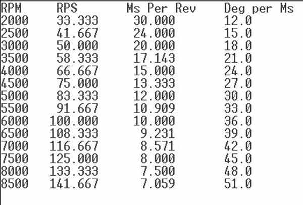
  calculates the coil dwell time compensation as a function of RPM. The idea is turn on
  the current in the coil 2 or 3 ms before you need the spark to fire.

  We can connect the O2 sensor as long as you are running no lead auto gas.
  A switch somewhere can turn it off and on. 100LL destroys O2 sensors.

  We got 8 channels of A to D and we are using only six.

  Paul Lamar


 I've run wideband sensors on cars with leaded race gas for considerable time with
 little ill effects.  To be sure, eventually the lead will coat the sensor, but if
 you're only using it for tuning, you can remove it once you're finished and plug the
 bung.

 Isn't there some built in dwell time compensation in the ms software? I was using the
 ms+spark-extra version. Have you checked that one out? It was several years ago, they
 may have integrated it with the baseline ms by now.

 http://www.msextra.com/doc/index.html#ms1

 http://www.msextra.com/doc/ms1extra/MS_Extra_Basic_Configuration_Manual.htm#rotary

 Josh


 Thats what I had in mind. By rearranging the chips I am going to wind up with a lot
 of real estate left over. The cost will be lower as well. Use of the CD4050 buffer
 instead of transistors  helps a lot as well.

 Yes on the dwell but I haven't found the source code yet. I suspect that was done in
 C version. I have to support this so I am sticking with asm.

 Paul Lamar

Paul,

Open this file and search for "dwell".  They've noted it fairly well.
I can't make heads or tails of the actual programming without studying
asm.

Josh


I did and this is what I came up with.
 ldhx    #0
        sthx    dwelldelay1
        sthx    dwelldelay2
        sthx    dwelldelay3
        sthx    dwelldelay4
        sthx    dwelldelay5
        sthx    dwelldelay6

Aha they used a look up table.

clr     lowresH			       ; low res (0.1ms) timer
        clr     lowresL			;
        lda     dwellcrank_f
        sta     dwelldms		; initial dwell period
        mov     #$10,dwellush		; } high speed dwell delay,
					; default of 4.1ms
        clr     dwellusl		; } until calc in main loop
        bset    SparkLSpeed,SparkBits	; At boot turn on low speed ignition
        clr     RevLimBits

>From the looks of it they struggled with the problem a bit :)

They are using a timer that increments or decrements every .1ms. Probably what
happens is they preset the counter in the timer as a function of RPM. Low count low
RPM. High count high RPM I think Then the timer interrupts the back ground program to
fire the plugs when it times out. Presto bingo.

Thanks Josh. I think I got it.

Here is how the Timebase Module works in the MC68HC908 :
Quote the MC68HC908 data sheet.
----------------------------------------------------------
Timebase Module (TBM)
16.1 Introduction
This section describes the timebase module (TBM). The TBM will generate periodic
interrupts at user selectable rates using a counter clocked by the external crystal
clock. This TBM version uses 15 divider stages, eight of which are user selectable.

16.2 Features
Features of the TBM module include:

• Software programmable 1-Hz, 4-Hz, 16-Hz, 256-Hz, 512-Hz, 1024-Hz, 2048-Hz, and
4096-Hz periodic interrupt using external 32.768-kHz crystal (We have)

• Configurable for operation during stop mode to allow periodic wakeup from stop
16.3 Functional Description

NOTE
This module is designed for a 32.768-kHz oscillator. (that is what we are using)

This module can generate a periodic interrupt by dividing the crystal frequency,
CGMXCLK. The counter is initialized to all 0s when TBON bit is cleared. The counter,
shown in Figure 16-1, starts counting when the TBON bit is set. When the counter
overflows at the tap selected by TBR2:TBR0, the TBIF bit gets set.

If the TBIE bit is set, an interrupt request is sent to the CPU. The TBIF flag is
cleared by writing a 1 to the TACK bit. The first time the TBIF flag is set after
enabling the timebase module, the interrupt is generated at approximately half of the
overflow period. Subsequent events occur at the exact period.

-------------------------------------------------------------------------
End of quote.

Piece of cake :) If I get this working that will allow using cheap LS1 or RX8 coils.
MSD CD's are expensive. Thanks for your help Josh.

Paul Lamar


--
The Rotary Engine News Letter. Powered by Linux.
ACRE NL web site. http://www.rotaryeng.net
You Tube key word PaulLamar2
Copyright 1998-2012 All world wide rights reserved.