Where do I connect the small 1" hose outlet used for the heater in
the car?  What type of hose should I use for the oil lines?
 Thanksfor any help Joe Berki

 The nipple for the heater is on the top of the rear(car) end housing.

 AN8 or AN10.

 Paul Lamar

Paul,
Does this heater hose connection get blocked off or does it get
plumbed into the system?

Joe Berki

Block it off if you don't have a heater on a pusher. On a tail
dragger vent it back to the water pump. Here is a jpg from my
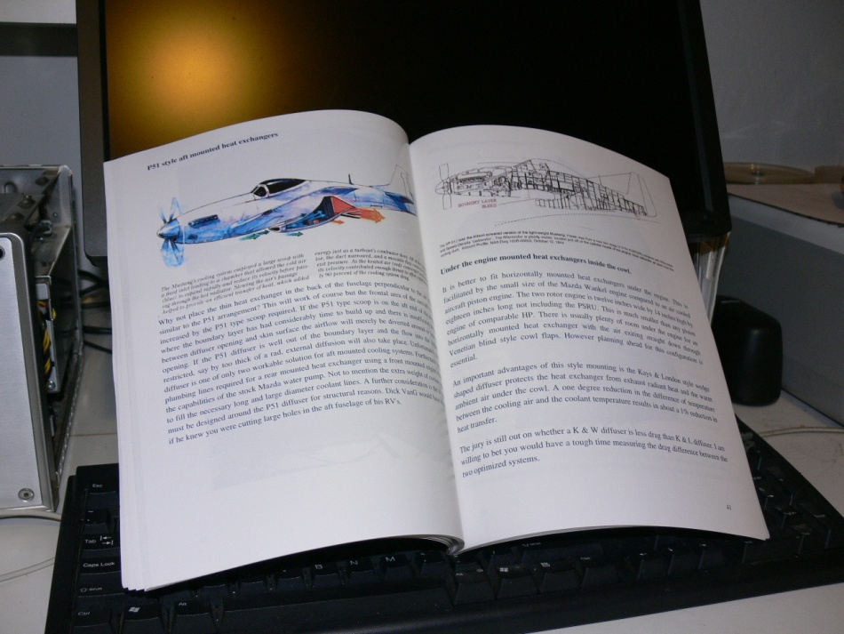
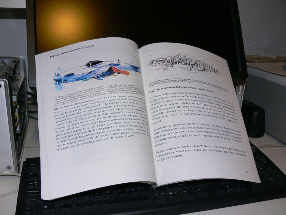
book.How to Cool your Wankel.

Paul Lamar

1"?? Most auto heaters have 5/8" hose from the thermostat housing
(engine  side) to the heater and 3/4" return to the water pump
suction. Some use both as 5/8". That looks like a de aeration vent
to the surge tank.

  Dale Davies

  Helps to fill the block as the engine is tilted up in a tail
 dragger. You get a big air bubble in there.

  Paul Lamar

 Paul,

 We ought to differentiate between the small 1/4" port on the top of
the rear side housing and the larger 5/8" (?) port just below the
oil filter pad.  We typically use the 1/4" port for an air bleed
back to the swirl tank, and the 5/8" port for a cabin heater, if
used, otherwise just block it off.  I wouldn't want to route it back
to the water pump as this is heated water.  If anything, I would
route it to the inlet side of the radiator.

 BTW, it isn't easy blocking the 5/8" port off as it is an oddball
 size, and there isn't enough material to drill it out to the next
 larger size.  I ended up cleaning it thoroughly and then filling the
 nipple with Devcon.

 Mark S.

 You are absolutely right.
 However the output part of the water pump is the inlet side of the
 rad :)

 Paul Lamar

 Correct me if I am wrong but does the water pump suction come from
the cool part of the radiator and the pump out pressurize the block?

Dale Davies

Yes.
It is more like the pressure is constant in the entire system.
There may be a small pressure drop across the pump but we use a 30
psi pressure cap to raise the boiling point.

What is rather confusing about the 13B Mazda water pump is both
inlet and outlet of the block water jacket goes through the pump body.

The pump is built into the front cover on the RX8.

Paul Lamar


Being a Journeyman mechanic I realize the cooling system is pressurized by
 the expansion of the coolant as it warms up. Once at operating temperature and
 stabilized, there is no more pressure increase. The coolant pump is the
 circulation "generator".

 Dale Davies

 Yes and the faster it circulates the better. The rate of heat transfer from metal to
 coolant gets better as the flow speed gets faster. Common sense. The bigger the fire
 hose the faster it puts out the fire.

 The real way to measure the engine temperature is place a thermal couple close to the
 combustion chamber near the lower spark plug. The metal temperature must be kept
 below 500 F or 260 C in any aluminum engine. CHT.

 Don't go on the water temperature alone. It takes a 3 HP pump to get enough water
 speed. When I first found the restriction in the 13B water pump back about 2002 and
 published the modification to eliminated it on here apparently Mazda engineering was
 listening.  They removed the restriction  in the RX8 water pump design. The RX8 WP
 gearing and impellor size is about the same as the 280 HP turbo 13B RX7 engine but no
 restriction.

 BTW an electric water pump is not going to cut 3 HP.
 1 hp is 746 watts. Three HP is 2238 watts. At 14 volts that is 160 amps! assuming
 100% eff. Nobody makes an off the shelf electric pump that uses 160 amps.
 Been there and done that.

 http://www.rotaryeng.net/electric-water-pumps.html


 Paul Lamar


 A more familiar concept may be wind chill.  Everyone understands that
 the harder the wind blows the colder it feels.  That's because it's
 carrying away heat from our skin at a faster rate.  That's why we all
 know to blow on a bite of hot food before putting it in our mouth or to
 sit in front of a fan when the weather is hot.

 Air is just another fluid.  The same principles that explain wind chill
 also apply to coolant fluid inside the engine and, in correlation,
 inside the radiator except that the heat is flowing into the coolant
 inside the engine and out of the coolant inside the radiator.  The
 faster the fluid flow the faster the heat is removed by the coolant.
 Faster flow causes increased turbulence which mixes the hot fluid
 touching the hot surface with the cooler fluid flowing by outside the
 boundary layer reducing the thickness of the boundary layer.

 The boundary layer acts like insulation.  We all understand that thicker
 insulation is more effective at reducing heat flow than a thinner layer
 of similar insulation.  You more often hear about delta T, the
 difference in temperature between the air in the system and the
 temperature of the heat exchanger surface, in air conditioning systems
 than you do in engine cooling systems.  Mixing of heated coolant in the
 boundary layer with cooler coolant outside the boundary layer increases
 the delta T between the coolant at the surface and the inside surface of
 the engine block resulting in faster heat transfer and better cooling.

 Any of you ridden a motor cycle at highway speed in hot weather?  As the
 air temperature increases the relative wind against your skin begins to
 feel hot instead of cool.  When the air temperature exceeds your skin
 temperature the heat starts to flow in the opposite direction heating
 you up instead of cooling you off.  And you thought that dude on the
 bike in the hot summer weather was enjoying the nice cool breeze.  NOT!

 Mark LaPierre

 Air is compressable as u stated Mark L, hydrodynamics is not aerodynamics
just ask boat designers. Cooling is effected by conduction. The boundary
layer impedes conductive cooling, the larger the boundary layer (this is
what insulation does) the less effective the conduction. Increasing flow
rate can induce greater turbulence and thus greater boundary layer disruption
( consider the difference of turbulent flow compared to laminar flow).
increasing flow rate also reduces the time the coolant spends in the
radiator reducing the delta T of the radiator. liquid conducts heat away
from the surface better than air, but an aerated liquid conducts even
better due to its ability to induce boundary layer disruption. Think of
the energy cavitation removes from a boat propellers thrust by inducing turbulence.

Next time you go flying, if there is a bit of dirt/dust on the
fuselage/wing, try writing your name in it. When you land your name
will still be there ( baring rain), this will demonstrate the effects
of the boundary layer, this is also known as the friction layer or
transition layer.
feel free to comment.

Graeme Riley

Air is a fluid. Water flowing past a boat hull builds a boundary layer too.

"Fluid dynamics textbooks usually begin discussions of this topic by explaining the
no-slip condition. This stipulates that the fluid molecules against a moving surface
do not slide (slip) over it. Instead, they are pressed against it and adhere to it.
The region of water pulled along with the hull is known as the boundary layer, and it
can take one of two forms -- laminar or turbulent."

"When the boundary layer is "laminar," it's thin and presents little drag. It's also
fragile, so it quickly breaks up into a thicker "turbulent" boundary layer as it
flows aft on the hull or foils. When turbulent, the boundary layer pulls more water
with it, creating more drag. Therefore, the first goal of bottom preparation is to
extend the laminar boundary layer as far aft as possible on your hull and appendages
by creating practically perfect surfaces in the areas where it can exist."

http://www.sail.ie/SW/Bottom%20Finishes.htm

Since the coolant coming out of the block is hotter the heat transfer rate to the
cooler rad is also higher.

http://en.wikipedia.org/wiki/Heat_transfer_coefficient
http://www.physicsclassroom.com/class/thermalP/u18l1f.cfm

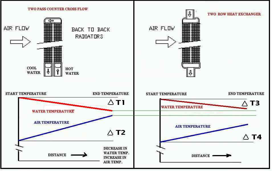
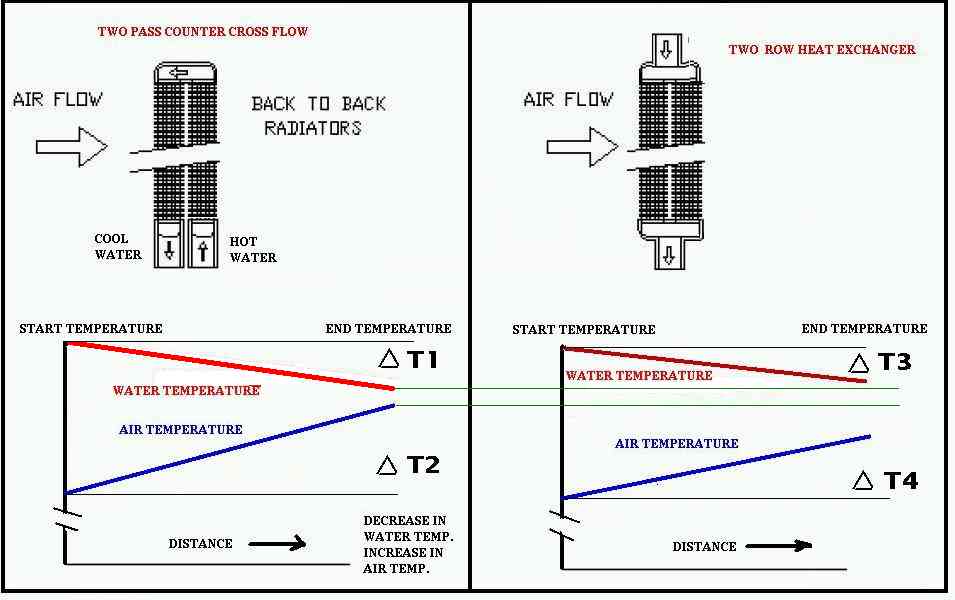
Now it comes down to rad configuration. A few facts. Having tubes of the same
diameter and area the more tubes the slower fluid flow in the tubes and the less the
pressure drop across the rad. Less tubes less area mean higher flow rate in the tubes
and the more the pressure drop. The coolant cools as it passes down the tube so the
heat transfer rate also decreases. Putting all these variable rates together gets
very complicated indeed. The bible on this subject is a book called Compact Heat
Exchangers by Kays & London. Here is a quote.

"It can be readily shown that for most flow passages that might be used for the heat
transfer surfaces of an exchanger, the heat transfer rate per unit of surface area
can be increased by increasing fluid-flow velocity, and this rate varies as something
less than the first power of the velocity. The friction-power expenditure is also
increased with flow velocity, but in this case the power varies by as much as the
cube of the velocity and never less than the square. It is this behavior that allows
the designer to match both heat transfer rate and friction (pressure-drop)
specifications, and it is this behavior that dictates many of the characteristics of
different classes of heat exchangers. If the friction-power expenditure in a
particular application tends to be high, the designer can reduce flow velocities by
increasing the number of flow passages in the heat exchanger."

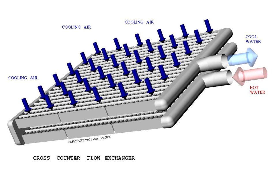
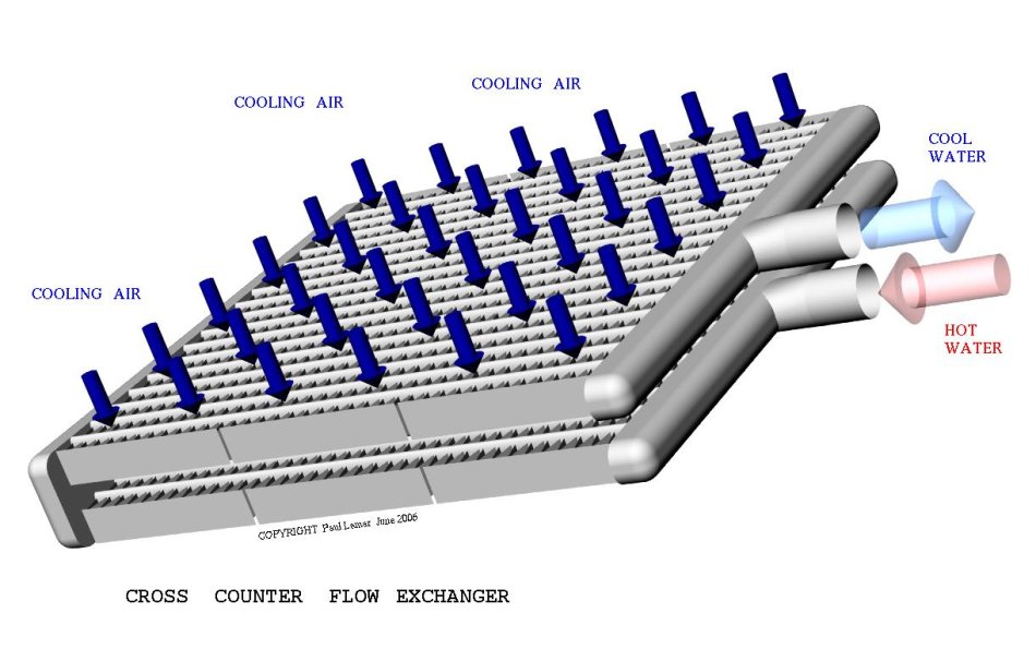
Here are a few jpgs from my book How to Cool Your Wankel.

Paul Lamar

The Rotary Engine News Letter. Powered by Linux.
ACRE NL web site. http://www.rotaryeng.net
You Tube key word PaulLamar2
Copyright 1998-2012 All world wide rights reserved.