I have 2 each of the coils used on the RX7- 2 leading units and
 2 trailing units.  The leading unit fires both plugs at once
 from a 5 volt trigger signal.

 My plan is to 1. use the OEM crank trigger unit to signal a 555
 board to fire the coils, one coil for each rotor.  2.  Use an
 HE sensor to fire
 the unit.

  It has been discussed that the plugs should fire at 22 degrees,
  but lately I have been reading 50 degrees- I assume that this
  is for dwell time?

  Should I set my timing for 22? Will the OEM unit work to fire
  the coils?  Does anyone know the output of the OEM trigger
  unit?

  Kevin Alderman

 Did you test that 5V trigger Kevin. I never got around to doing
 that.

 I'll make sure to put CAS conditioning on the board. I was
 considering using just Hall Effect sensor as they are much
 cheaper.

 The 50 degrees (not cast in concrete yet) is to give the
 trigger board time to adjust the timing to 22 degrees BTDC at
 all RPMs.

 You will need two CAS. One for each rotor. Also a trigger wheel
 with two tits.  Tits are clocked 180 degrees apart.  This will
 give some back up as the engine will run on  one rotor.


  Paul Lamar


 Yes I tested it. 12 volt primary with 5 volt trigger, common ground. I was
 using an old set of plug wires, and found a crack in the insulation. A 3
 inch arc to the knuckle.

 The oem cas has 2 sets of points. One is 2 points 180 apart, the lower is
 24 teeth. I was going to use the top set for initial testing of the
engine.
 I have the oem unit in place at 22 degrees at the moment.

 Kevin Alderman.

 Good info. Thanks Kevin

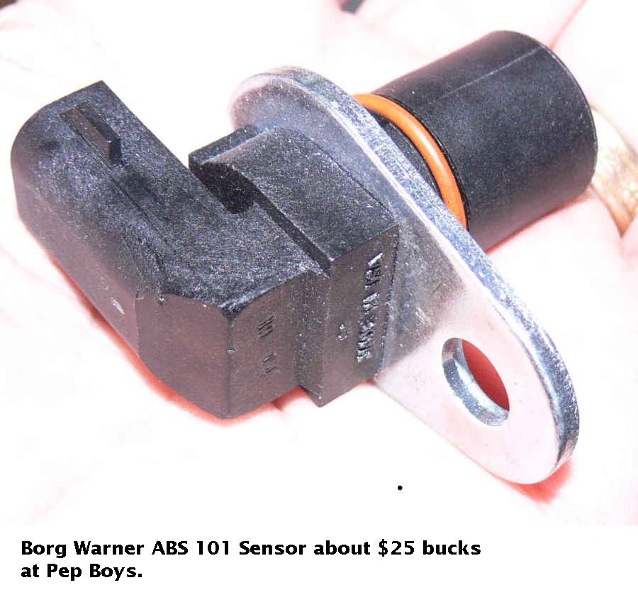
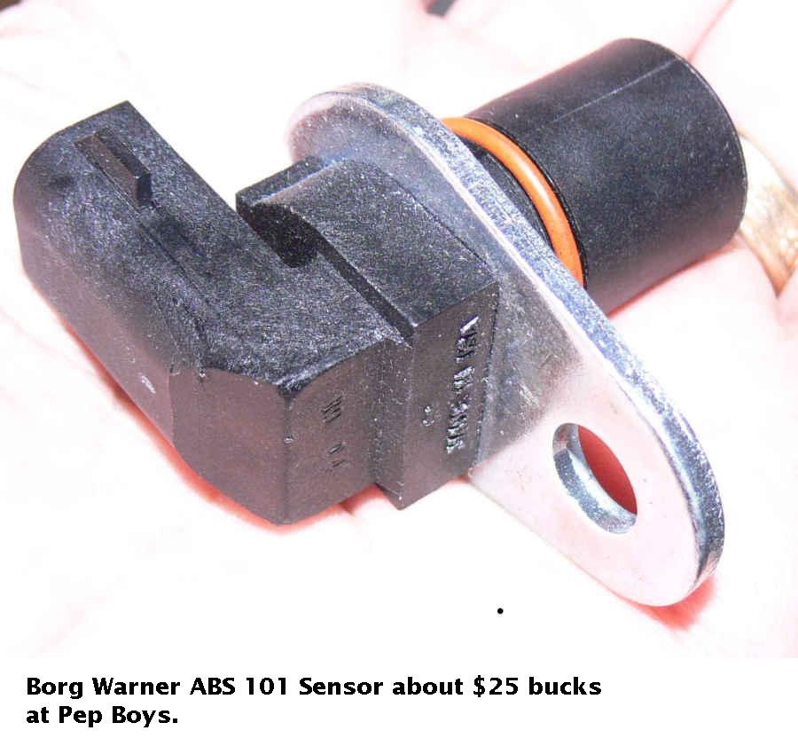
 BTW an ABS sensor is the same as the Mazda CAS and is a lot cheaper at
auto parts
 stores. About $20 as opposed to $100.

 Also BTW the 2nd gen CAS that looks like a abbreviated distributor can
fire RX8 and
 LS1 coils with the circuit I am working on.

 Paul Lamar

Do you know what the output waveform and voltage is for the short OEM cas
(abbreviated distributor)?

I may hook up the extra OEM cas that I have to a drill and see if it will
trigger the coil to fire. :)

Kevin Alderman

They all look pretty much the same. It is just a coil of wire wound around a magnet.
It is easy to make your own.

Here are some scope pictures and other stuff.
The voltage generally goes up with RPM. Starts out at least +/- 5V at cranking speed.

BTW for this low speed stuff you can get free scope software for your computer that
uses the audio mic input.
http://www.zeitnitz.de/Christian/scope_en/

-------------------------------------------------
This abbreviated distributor device is very interesting in that it rotates at half
e-shaft  speed. That is why there are two tits in there on the top wheel.

It was totally unnecessary to do that as the rotary fires every rev unlike a 4 stroke
piston engine. Later system did away with it proved by the 3rd gen and RX8 engines
that don't have this device. Obviously the technology was left over piston tech.

The lower pick up sees a wheel with 24 teeth on it so that is one pulse every 30
degrees of e-shaft rotation. This signal tells the computer the RPM. The upper pick
up sends a pulse to the computer every one e-shaft rotation so I was wrong about it
working with my new ignition board. You will still need one wheel with one tit and
two pickups spaced 180 degrees apart.

Paul Lamar

--------------------------------------------------------------------------------
Change of direction here. The hardware was getting too complicated and the opamp was
recalcitrant as opamp are wont to do.

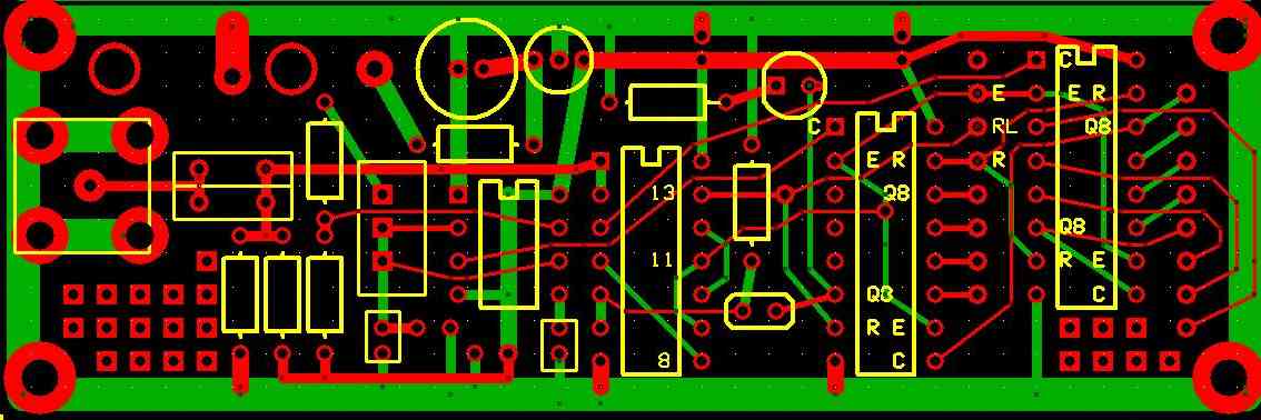
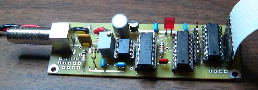
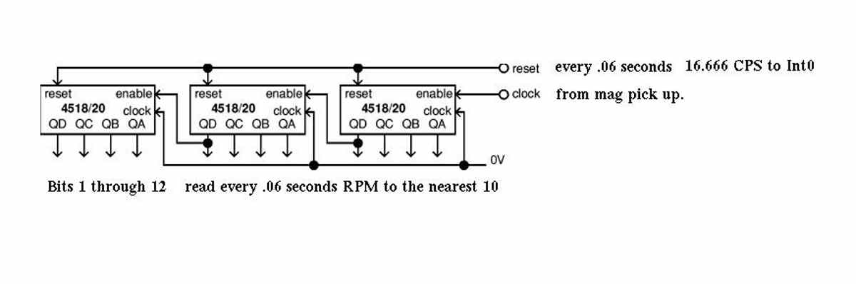
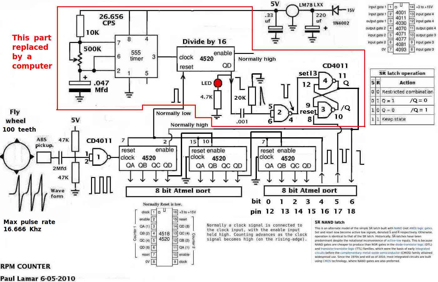
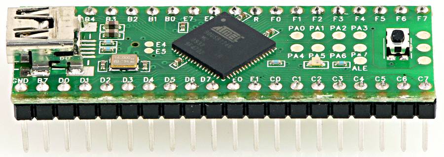
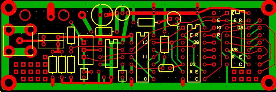
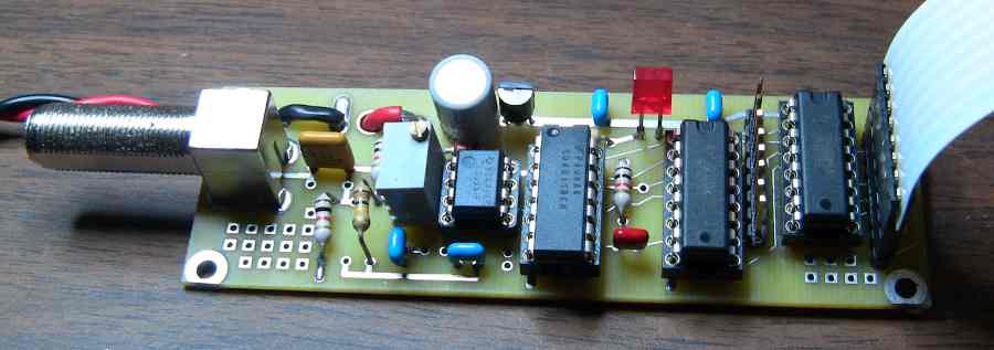
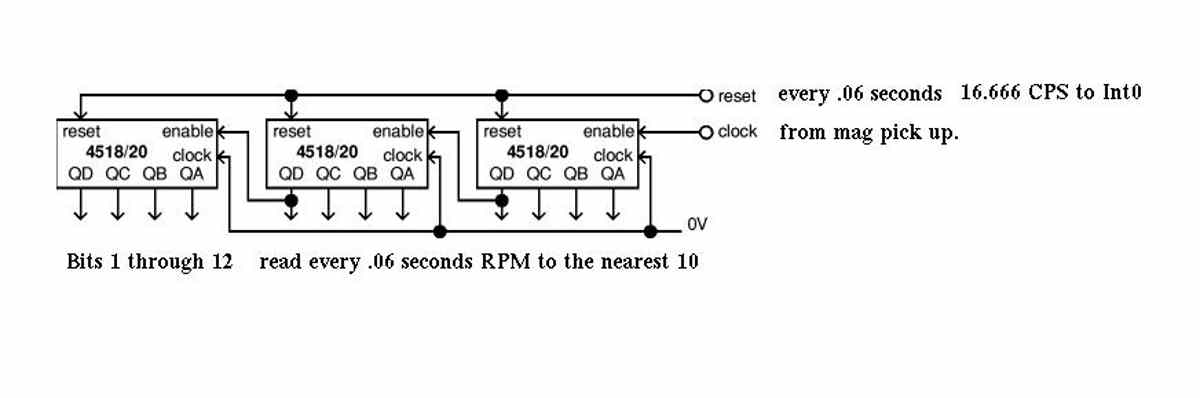
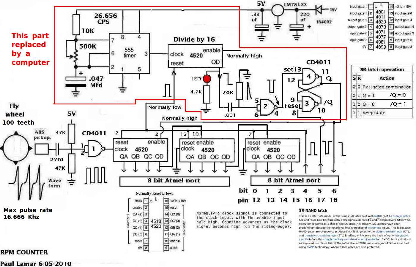
I have decided to use a hardware counter to read the teeth on the flywheel to
determine the RPM. Much like Mazda and Tracy do. I already built this counter and
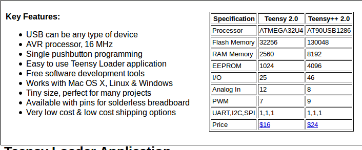
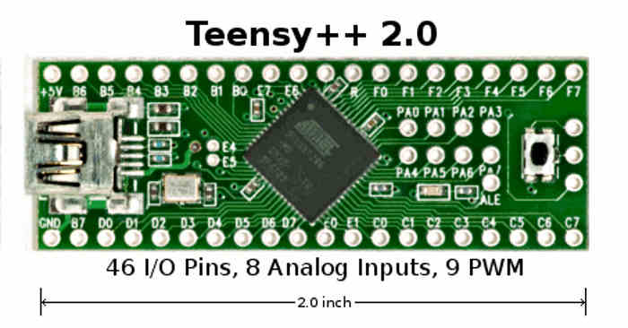
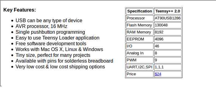
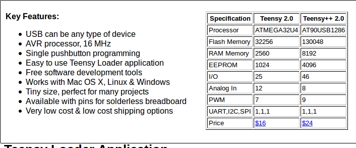
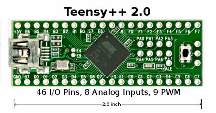
tested it. Pictures are attached. I was going to use it with a ZBasic $100 computer
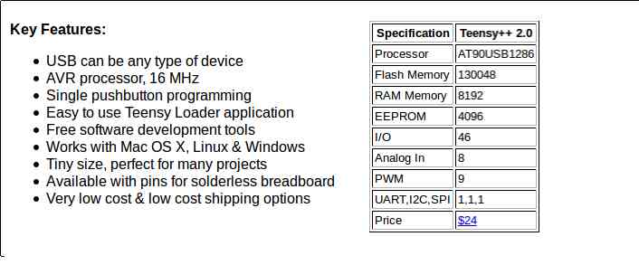
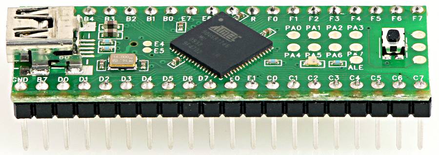
but a much cheaper one ($24) has emerged on the market place.
http://www.pjrc.com/teensy/index.html

Way overkill for our needs but hey... what the heck... only $25.

Here is reiteration of the complete low cost stand alone ignition problem.
We have a Mazda rotary engine that rotates up to 10,000 RPM.
We need a stand alone ignition system. One per rotor (Mazda engines come in one two
or three rotor configurations)  firing two GM LS1 or Mazda RX8 coils
with built in igniter's triggered by an up-going 5 volt low current  pulse.
This pulse normally comes from a computer. Each rotor has two plugs and two coils
that fire at the same time.

We can look at the teeth on the flywheel with a off the shelf magnetic sensor to get
a rapid high resolution determination of the RPM.
There are about 100 teeth so max pulse rate from this source is 16.666 Khz.
I have no problem using an external hard ware counter for this purpose.
See the attached jpgs. There is also a real time clock so the number of pulses coming
in from the flywheel in a fixed time period can be determined.


We also have a sensor on the front pulley that sends out a narrow pulse  at 50
degrees BTDC. 500 RPM this comes in at 8.33 pulses per second. At 10,000 RPM it comes
it at the rate of 166.66 pulses per second. I would like this pulse fed into a hard
ware interrupt. (IRQ).

The coils can remain on for a max of 4 ms. If longer than that they over heat.
So we will use a CMOS one shot set to 4 ms to fire the coils. When the one shot goes
low that sparks the plugs.

The job of the real time clock interrupt is to disable the RPM counter, read it,
reset it and store the RPM. Then when the interrupt comes in from the tit 50 degrees
BTDFC comes calculate the delay necessary to fire the one shot so the timing comes
out at 22 degree BTDC. There are other ways of doing it in software but I want to
keep the software real simple.

That's it.

Works with carbs or megasquirt 1 V2.2.

Paul Lamar

--
The Rotary Engine News Letter. Powered by Linux.
ACRE NL web site. http://www.rotaryeng.net
You Tube key word PaulLamar2
Copyright 1998-2012 All world wide rights reserved.