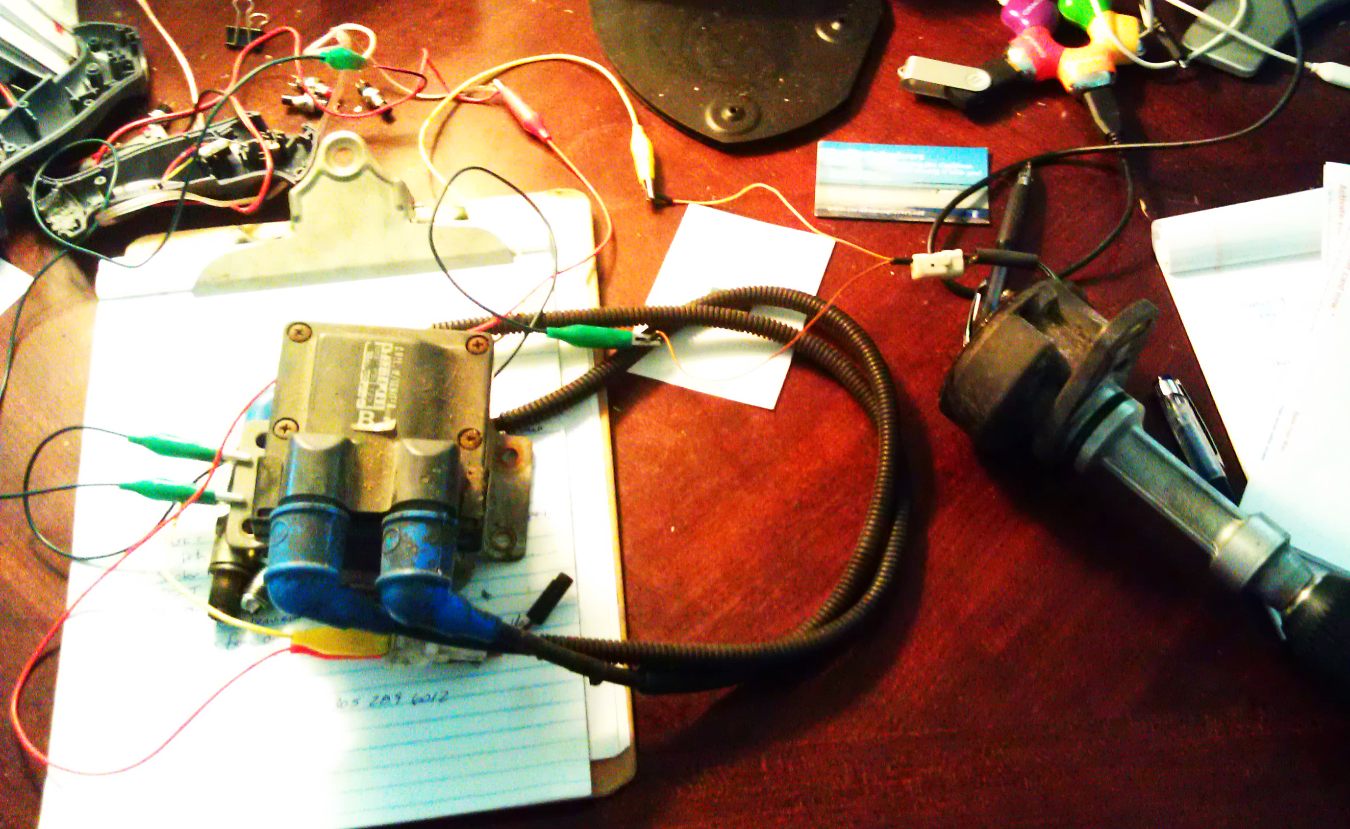
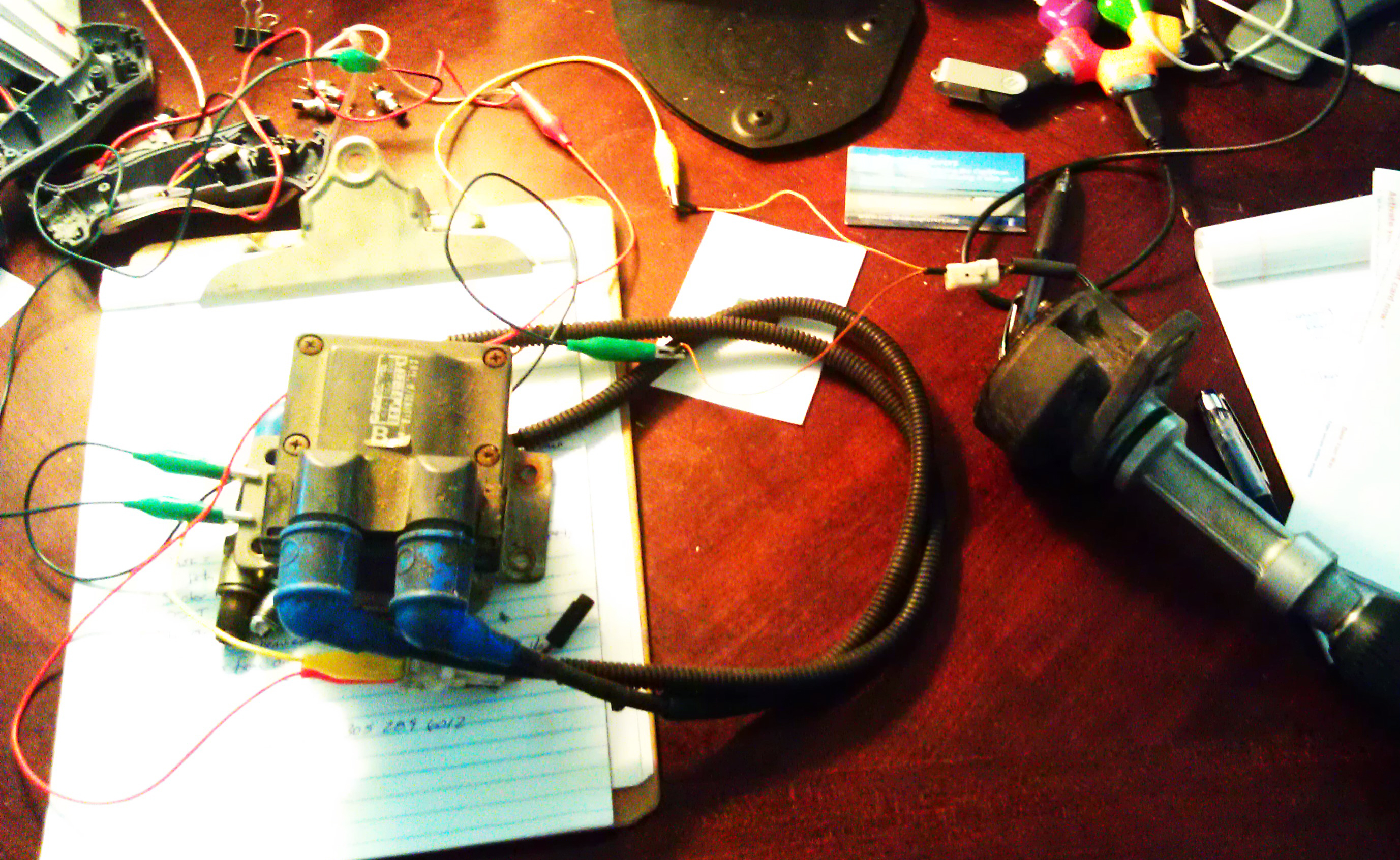
I just connected the OEM coil with the self igniter- the one that fires
both plugs simultaneously. I connected the 12v lead to the battery (tan
wire) and the trigger to the output of the sensor in the OEM distributor
unit.

At 450 rpm the unit fires without any help from an electronic unit. I know
this would likely not fire during cranking without a really good battery,
but it confirms that if you could spin it fast enough, the unit will fire
without help from a computer.
My drill only runs to 1500 RPM, and at this speed the spark is noticeably
hotter than at 450 RPM.
On the scope, at 400 RPM the output voltage is 2.5 volts, at 1500 RPM the
voltage is 3.5 volts.

With this info, I will begin to design and construct an electronic unit
that will fire the coils, and later try to work in a bit of advance. My
board will use an Atmel 328 chip operating at 20mhz, one unit for each
coil. If this system proves successful, I will try to incorporate the
programming into each unit to fire both rotors, which will provide
redundancy.

To test fire the engine, I plan to pick up a pair of outboard carbs from
the local boat mechanic, and install them directly to the P-ports.
Hopefully soon I will get to hear noise and see smoke (the good smoke not
the bad smoke).


Kevin Alderman

If you have a scanner draw a schematic and send us a jpg scan.
No scanner... use MS Paint and save as jpg.

The increase in voltage with RPM is typical. The igniter must have a pulse stretcher
built in as otherwise the coil would not have time to build current flow and a
magnetic charge. The CAS trigger pulse is less than a millisecond wide. It takes
several milliseconds to charge a coil.

I have never tried what you are doing. Interesting.

Set initial timing to 22 BTDC. If you get it to run check the timing with a timing
light at idle and at high RPM because in theory it will retard. The EFI computer is
programed to compensates for this effect. As I recall 7000 RPM is 8.6 milliseconds so
if the igniter stretches the CAS pulse 4 milliseconds you have lost your advance.

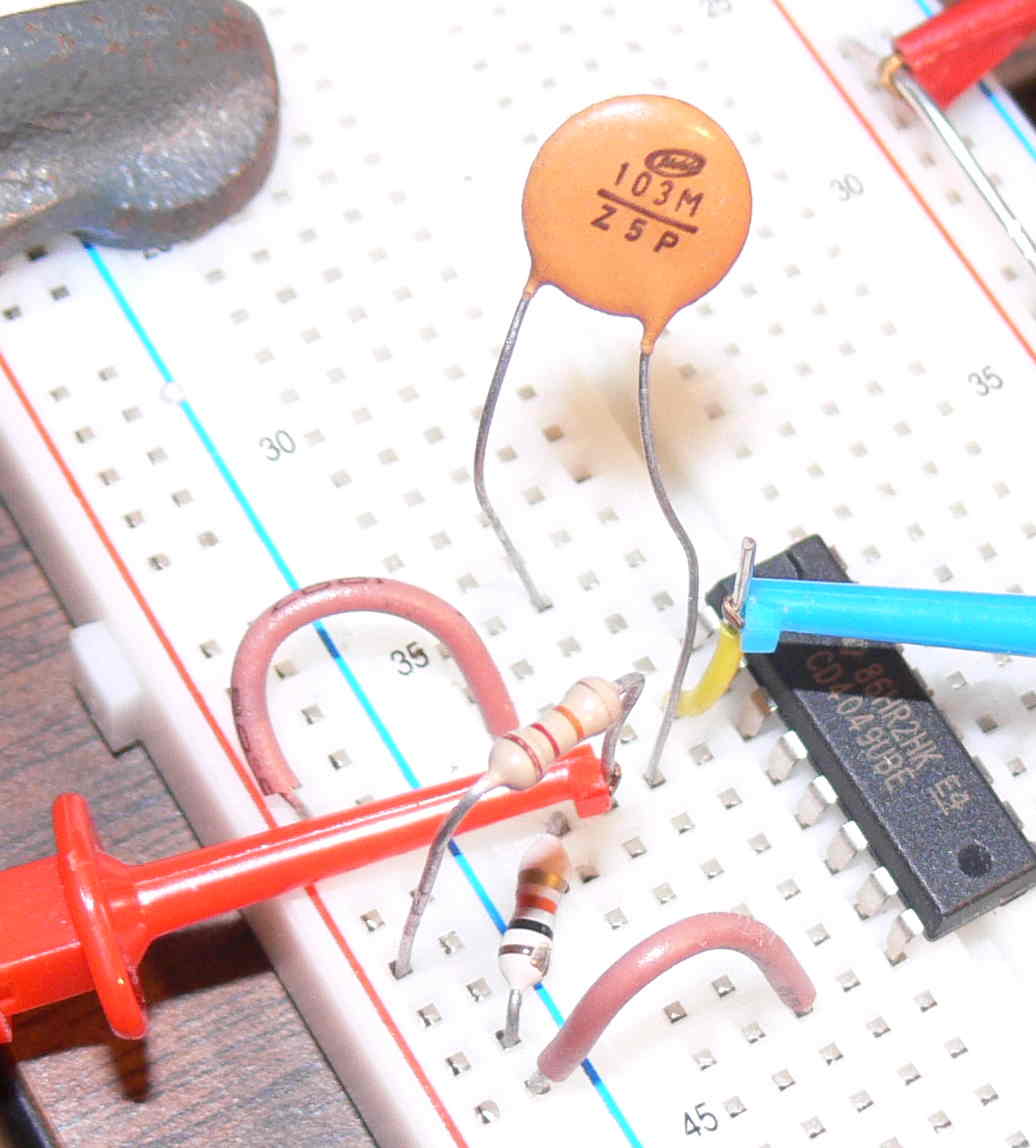
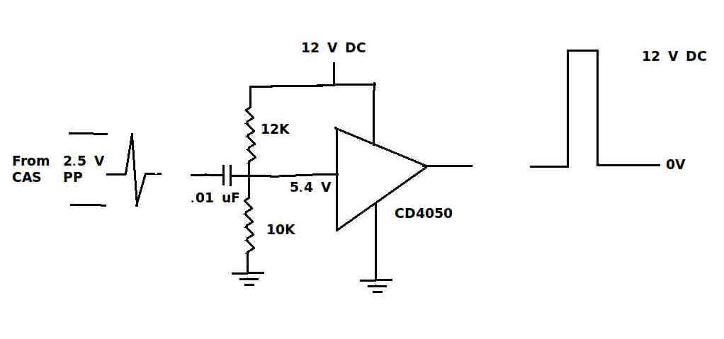
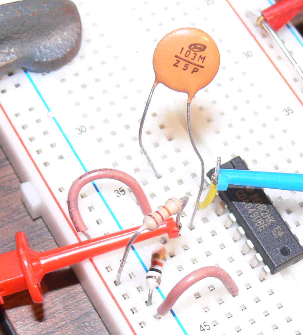
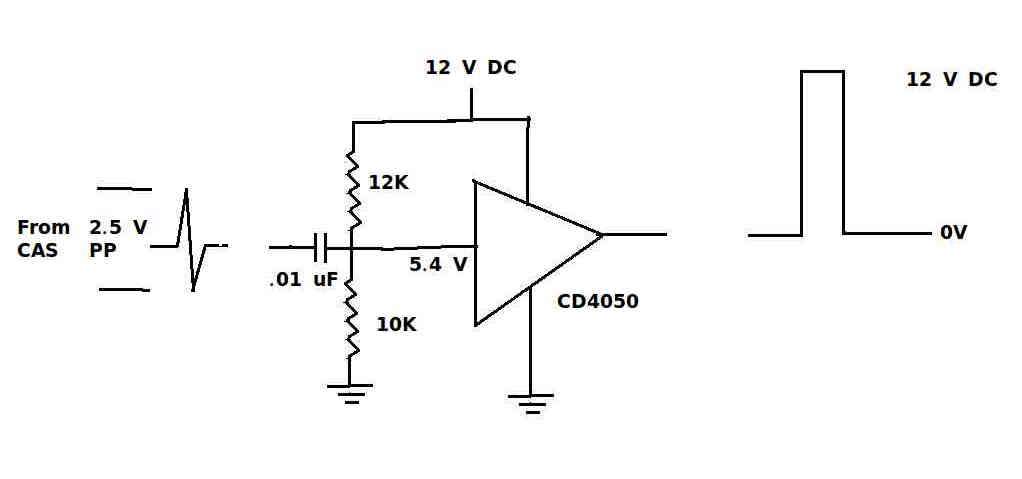
Here is a dwg of a circuit that will amplify the CAS trigger at low RPM and it will
work at 12 volts. I have used this circuit  many times in the past 40 years. The
CD4050 chip is bullet prof.

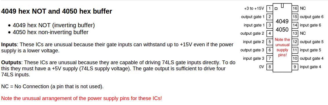
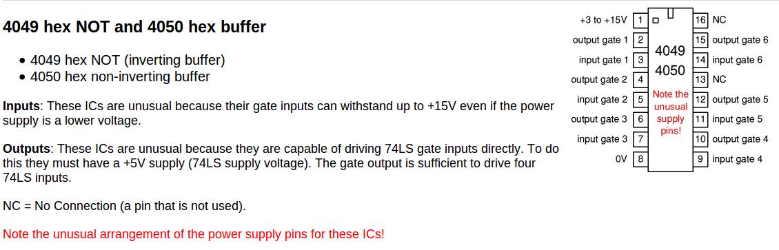
The CD405 is a 50 cent chip likely to be found in radio shack. No 5 volt supply is
necessary. Works up to 18V.

It would be wise to put a 5 Volt zener on it because I don't know what the stock 2nd
gen igniter, like you are using, will tolerate as a trigger. I think they are
designed for only 5 volts.

There is a remote chance the igniter wants to see a down going pulse.
If that  is the case swap the resisters. It will probably work with a .1 uf cap as well.


Paul Lamar

--
The Rotary Engine News Letter. Powered by Linux.
ACRE NL web site. http://www.rotaryeng.net
You Tube key word PaulLamar2
Copyright 1998-2012 All world wide rights reserved.