Kevin, your experiments with the 2nd gen igniter gave me another idea to
   try
   for a cheap CD system. The 2nd gen lower mag sensor puts out 12 trigger
   pulse per rev.

   Feed that to a FET that turns on and off the primary of a pulse
   transformer.
   At 400 RPM that is 80 PPS. A simple circuit can double that to 160 PPS.
   at 8000 RPM it is 266 PPS.

   A common low cost ($30) 220 V  60 cycle control transformer is CT 24
volt
   to 220
   volt. Use the 12V half to jack  the voltage from 12 Volt square wave to
   220 volts AC.
   With a full bridge rectifier  or voltage doubler circuit you might get
   near 400 volts
   DC. Use that to charge the CD capacitor.

   The old Heath Kit CD ignition  used a control transformer and a
  mechanical
   vibrator
   to generate the high voltage back in the late 50's and early 60's.

   You can find a manual on ebay. Heathkit Manual Capacitive Discharge
   Ignition

   If you want a cheap pulse transformer they can be had from salvaged PC
   power
   supplies. It takes a lot of fooling with them to find the windings that
   work.

   A CD systems trigger with no delay.

   BTW with AVR development board are you using?


   Paul Lamar


   -------------------------------------------------------

   I just had a better idea.

   Use an ABS sensor on the flywheel teeth and get a much higher frequency.
   4000 pps at 400 RPM and 8.3 Khz at 8000 RPM. Now we are in the range of
   switching
   power supplies found in PC. Much smaller transformers.

   No 2nd gen CAS needed. Will work with any rotary  12A to RX8 that uses a
   starter.

   Here are some typical PC power supply transformers and CD caps.

   Paul Lamar

   I was fooling with a transformer out of a PC power supply. I found a
   couple of
   windings  that seemed to work. 10 volts in pp gave 100 volt out pp.
   This was at 20 Khz but it worked over a wide freq range.

   Remove the primary, use larger wire and cut the number of windings by
   about 1.3rd.

   Paul Lamar


   I think I  found a source for transformers. If the price is right I will
   get some and
   build some CD's. These are so cheap we can use one per plug. I'll donate
  a
   set if you
   are willing to test them. You must be in the U.S. so I can get there to
   witness the test.

   Kevin, if you don't get yours to work I will be in Florida about Oct
1st.
   I might
   have them done by then. Those 2nd gen Mazda coils make great CD coils
  when
   removed
   from the igniter's.

   In the past I tried to build CD systems but with out good results. I
   thought the HV
   had to regulated. That was the main problem. I now realize that is not
   neccessary as
   the outboard type are not regulated. Nor was the Heathkit for that
  matter.
   In other
   words it is open loop. Here is an open loop CD system using a 555
   oscillator at 68 Khz.

   Paul Lamar

   I am not sure I will be done by Oct 1, but I work every time I get a
  chance. I have read the discussions about the CD ignition and although it
  looks good on paper, I am skeptical. I am a boater (USCG Licensed
Captain)
  and have spent lots of time on the water in everything from small
  outboards
  to big tug boats and commercial vessels- My experience tells me that 1.
  The
  only  boats that have left me limping home are outboards, and 2.
  especially
  before the past 5 years or so ago more often than not due to a bad power
  pack that controls the ignition. While the reliability of outboards has
  increased substantially in the past few years, I still do not trust it on
  an airplane. I remember a particular boat that we had- a 2006 model 35
  foot
  center console with 3 outboards. I seldom ran out a tank of fuel that we
  didn't come back with one engine kicked up and not running. We had 3
  engines, and most of the time only were able to use 2 of them.

  More recently, for outboards we have a 150 Yamaha 4 stroke EFI, and a
  Mercury 25 four stroke EFI. Both have suffered fuel problems, electrical
  issues, and the Merc- only 3 years old- needs both electrical work and
EFI
  work to even run again.

  On the rotary, I am encouraged by my weekend experiments- with redundancy
  and simplicity in mind, here is what I am planning:

  I will initially use an Arduino Pro Mini (Atmega 328 clocked at 20 mhz at
  5.5 volts) with a program just to fire the coils through a Darlington or
  MOSFET transistor.  A wasted spark setup would be easiest, but a coil
  firing twice as many times as it should will generate excess heat, and
  will
  shorten the available charge time by half. My tests for this part will be
  completed using carbs from a local outboard repair shop- again
simplicity.
  I am not looking for power yet, just the ability to test the engine at a
  variety of RPM settings and put a few hours on it. The Arduino has 14 I/O
  ports some analog and some digital. I can use the outputs to record RPM
  and
  other variables. I also have a similar Arduino already set up as a
  datalogger. Right now it records movement, temps, etc, but I plan to
  modify
  it with different sensors to record the engine parameters. This unit will
  likely be a permanent part of the plane.

  http://arduino.cc/en/Main/ArduinoBoardUno
  These boards are manufactured by lots of different people now, and the
  ones
  I have have interchangeable crystal oscillators. Clock speed now is 16mhz
  at 5v, 20 at 5.5v. I think this will work especially for testing, but if
I
  need to push it up I will.

  Back to the ignition- assuming satisfactory results, the final design is
  anticipated to consist of twin ignition computers in separate cases
  connected in an A/B configuration.  I used the attached schematic as a
  base, with a few changes- I removed the switch shown. In its place I
  connected one of the leads of the CAS to the Base of the Tx. I connected
  the other to a common ground. I connected the common ground to the frame
  of
  the coil. I fed 12v to the tan wire, and the trigger to the red wire.
Just
  for this test, I didnt use any resistors or diodes, capacitors, etc. I
  just
  wanted to see if it would work. The final circuit will have a few more
  components I am sure. And, I used the Darlington Tx because that is what
  is
  what I had in the goody box.

  That is the update for the moment-

  Kevin Alderman

  I assume the  Arduino is programed in C. Strange for a boat captain to be
  proficient
  in C. :) I will spend two months in Orlando and take a few days off to
  visit the keys
  anyway. I think I have been on your island and seen your house at the
  airport.

  I have a real old friend that lives in south Florida by the name of Dave
  Smith.
  He is also a licensed boat captain and a road racer. I think he still
  runs an RX7.

  BTW look at FET's instead of darlingtons. They have much lower on
  resistance and
  therefor generate less heat which translates to more reliable.
  Darlingtons are old
  school :)

  Paul Lamar


  Thanks Paul;
  I would have used FETs, but I didn't have any in the goody box. My
  intention this weekend was to just see if I could get the coils to fire.
  Now that phase 1 testing is complete, we move on to phase 2.

  As far as proficient in C, that might be a bit of a stretch. I am 45,
  straight out of high school I started an electronics engineering course.
My
  last semester the class canceled due to lack of interest- took 10 to keep
  the course we only had 8 left. It was at this point that I started
business
  as a Contractor eventually having 74 employees and many headaches. Over
the
  years I would go back to the local community college for courses here and
  there- programming, physics, lots of calculus, etc. Always learning. As
you
  know after all of your years, it is mostly how your brain works, not what
  stuff you memorized along the way. So, I find a problem, learn as much
as I
  can about it, and then proceed to solve it one step at a time.

  For the beacon on the plane I made a 555 timer connected to two red LEDs,
  one on top and one underneath. Works well and I am positive it will meet
  the lumen requirement, BUT, I plan to make a step up circuit to boost the
  voltage to 36v to make them really bright. I took apart a power supply
and
  a couple of amplified car stereo units, so now my goody box has more
stuff
  in it.

  Kevin Alderman


 Check this out- one made to communicate with Android!
  http://www.mouser.com/arduinoandroid/
 Might make it easier to output the display info to an android on the
panel-
 Yippee, I get another project to test out!

 Kevin Alderman

 Kevin, this can be programed with arduino software. $27. If I don't use
it I will
 send it to you.

 Paul Lamar


Thanks, but if I get my unit running off the board and software, I can
email you the code and you can experiment. I picked up some FETs today, and
if I get time I may get it on the board this week for testing. I made the
engine mounting plate today, another day or so and the engine will be
bolted down, and hopefully closer to firing in a few days.

Kevin Alderman

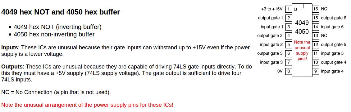
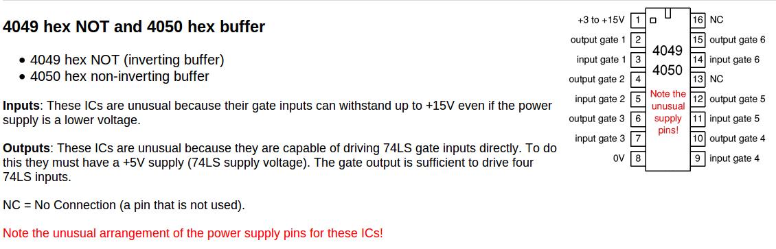
These things make the best FET drivers in the world. Parallel about three of them.

Paul Lamar
--
The Rotary Engine News Letter. Powered by Linux.
ACRE NL web site. http://www.rotaryeng.net
You Tube key word PaulLamar2
Copyright 1998-2012 All world wide rights reserved.