Henry Nee came up with a great idea. If we standardize on a spreed sheet
   format for
   the mixture map we can share (even across programs). Yours and mine.

   This is the megasquirt format.
   It is broken down into 8 RPM's and 8 manifold pressures.
   Usually EFI programmers interpolate between these values.

   Keven, Please do this. It will help other people greatly.

   The idea is to be able to dump the table to a PC through the USB and edit
   it in the
   PC as necessary. Then reload it back into the chip.

   This is how it is done in Megasquirt.

   These are median values so they can go down to zero and up to 255 as
   necessary.
   They are also a function of the injector used. If you find that the
 values
   are all on
   the high side you could go up on the injection pressure or use larger
   injectors.
   Same vice versa.

   Tracy uses two staged injectors per rotor so there could be one table for
   each
   injector. The tables only require 65 bytes of flash memory each.

   I am using one computer per rotor.

   Paul Lamar


  Paul,

  You said earlier that the rotary typically uses a fixed 22 deg BTC firing
  arrangement with both plugs firing simultaneously- are the turbo guys
 using
  this setting as well?
  Normally when using higher boost levels, the timing is retarded several
  degrees as boost pressure increases. I was thinking that my timing table
  would have a few more lines than standard to allow for this. As pressures
  go above standard i.e. 31 inches, the timing would progressively be
  retarded. I have read in more than one place that using as little as 8 psi
  of boost in racing engines requires the timing to be retarded to as little
  as 5 degrees BTC. At 8000 RPM this doesn't give much time to burn the
  fuel/air charge, but this setting is selected to prevent pre-ignition.

  Any thoughts?

  Kevin Alderman

 As far as I know they do. They may retard. Are you doing a turbo? It has
  it's advantages if one plug goes out.

  Well what ever you do keep the ign and inj tables the same so others can
  use them.

  I am going to keep it simple and let the CAS fire the 2nd gen ignition
  directly.

  If the computer fails the engine will still run using a small tube into
 the
  intake with a needle valve from a header tank.  Worked for the wright
  brothers :)

  "The Wright Brothers 1903 aircraft piston engine fuel flowed through a
  small metal fuel line from the high mounted tank to the engine.  The fuel
  dripped into a flat, enclosed pan that sits on the top of the engine.  The
  floor of the pan was hot because it sat over the hot engine cylinders.
  Air
  was drawn into the pan through the air intake, because of the action of
 the
  pistons.  The combination of air being drawn over the fuel and the heat of
  the floor of the pan caused the gasoline to evaporate."

  "The fuel flow to the engine was adjusted while the aircraft was waiting
 on
  the launch rail.  When the engine was running as fast and smooth as
  possible the aircraft was ready for launch.  The pilot had a control lever
  which was connected to a cut-off valve to stop the engine at the end of
 the
  flight.  The brothers had no throttle or engine control during the 1903
  flights.  The Wright "carburetor" and intake system had no moving parts.
  Without the moving parts, the brothers engine ran at just one speed
  throughout the flights of 1903."


  http://www.rotaryeng.net/simple-cheap-555.html

  Klaus set that up recently and he found it works much to his surprise. No
  carb no
  nothing, nada :)

  Paul Lamar


 I was planning to add another sensor to the factory CAS, 90 degrees from
 the first. Separate boards will read each signal and fire each rotor-
 similar to what you are doing. I have 3 boards- identical except the third
 is equipped specifically to output to Android software. The third board is
 even bluetooth capable, so I dont even have to use usb if I dont want to.

 The OEM CAS turns half engine speed. It has 2 tits on top, and 24 teeth on
 bottom. The sync signal will be firing signal for rotor 1, and RPM will be
 read from the 12 tooth count off of the bottom wheel. Count to 12, start
 over. See how long it took. Do it again.

 The third board is capable of running both rotors if need be, and can be
 programmed to read all of the same inputs and give the same outputs as
 board 1 and 2, again redundancy. The switching might be interesting to
 design, but one step at a time.
 The programming for each  board will essentially be the same, it is just a
 matter of switching over the units in the air when everything else is going
 wrong.

 Paul, after you get your boards going, you could port them to the board
 that I have and read them on any android tablet. I am going to work on the
 EFI part first, and then port the output to the Android board so that I can
 read it on my tablet. After I get it working, I can send the code and info
 to the group so that any of us can do it. If I can get it to work, this
 board could be wired to read the output of Tracys computer and log
 everything to a tablet that we can use while we fly to see what is going
 on. Everything that Tracys computer is reading, as well as everything it is
 saying to the engine too. If my system works as planned, I will be able to
 use the touch screen (in calm air!) to alter the engine while I am flying.

 Kevin Alderman

 I just got my board to blink an LED :)
 Written in BASIC no less. It blinks at the rate of just over 1.5 seconds
 due to the
 built in BASIC delay routine in the test program.

 BTW I have decided to determine the RPM by accumulating a count on one of
 the
 internal timers. If I divide the 10 Mhz (10,000,000) osc clock by 100 I
 get 100K. The
 internal timer divides that again by 12 giving me a count of 8333 CPS.
 At 2000 RPM or 33.333 Hz the 22 degrees BTDC passes every .03 seconds. So
 the 8 bit
 count is 8333 x 0.03 seconds is 249. Just about the 255 limit of the 8 bit
 counter.
 At 8000 RPM or 133.3 Hz or .0075 msec the count would be 8333 X .0075 or
 62.

 In other words the RPM is updated once per rev. Upon TDC the counter is
 read and
 reset to start counting over and the current RPM number is placed in
 storage for use
 by routine that looks up the required injector pulse width in the table.

 There is not much more to the simple program as I will generate the pulse
 width in
 simple hardware. The injectors will also fire at 22 degrees BTDC more or
 less.

 That should give plenty of time to send engine data like MAP, RPM,
 injector pulse
 width and intake air temperature out the USB port to Kevin's computer.

 Once you know the injector pulse widths you know fuel flow so if you have
 a GPS
 module you can calculate real ground speed and real miles per gallon.
 http://en.wikipedia.org/wiki/NMEA_0183

 "NMEA 0183 is a combined electrical and data specification for
 communication between
 marine electronic devices such as echo sounder, sonars, anemometer,
 gyrocompass,
 autopilot, GPS receivers and many other types of instruments. It has been
 defined by,
 and is controlled by, the U.S.-based National Marine Electronics
 Association."

 ........time.usec...lat............long.....alt ..heading ....speed..
 etc....
  $GPRMC,081836,A,3751.65,S,14507.36,E,000.0,360.0,130998,011.3,E*62

 See GPRMC attachment.


 Paul Lamar


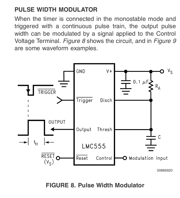
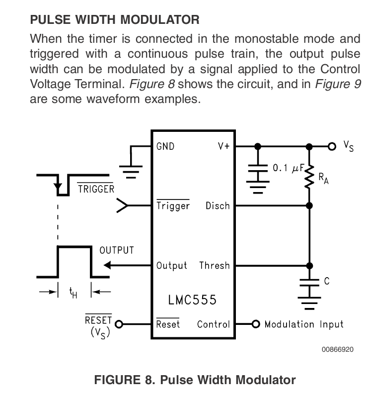
Sounds good Paul. Are you using the 555 timer to generate the pulse width?
If so, how are you varying the LC in this circuit to change the timing and
pulse?

Kevin Alderman

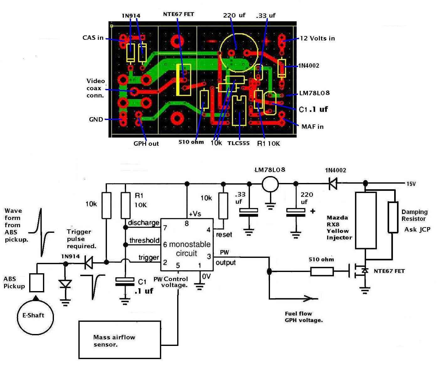
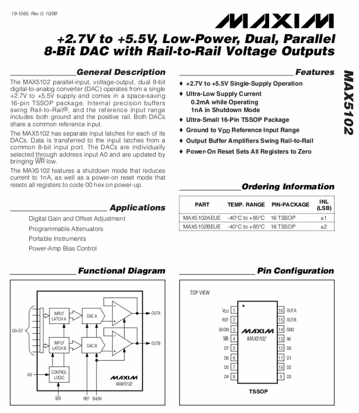
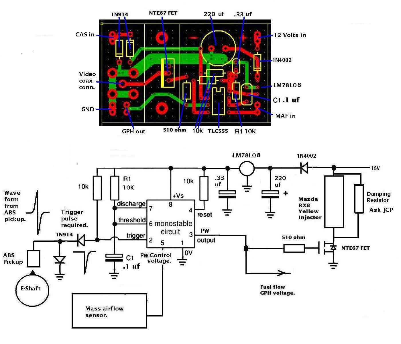
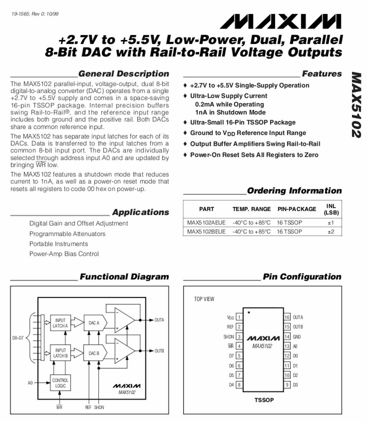
Yes. The CMOS 555. I ordered the wrong DAC. So I hope I ordered the right one this
morning. It will arrive tomorrow so by tomorrow night I will know more. There are a
zillion of these things with no two alike. I know the CMOS 555 is OK. The beauty of
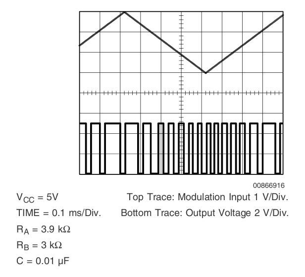
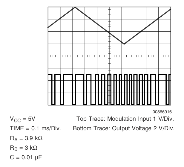
it is the 555 can trigger the injector FETs directly. The CMOS 555 has a pin that
controls the pulse width. It is very precise. You store an 8 bit value in the DAC
through one port and then trigger the 555s. Two 555s. One for each injector. The DAC
output goes to pin 5 on the 555. CPU makers ought to build these into the chip.
Another idea years ahead of its time :)

Paul Lamar

--
The Rotary Engine News Letter. Powered by Linux.
ACRE NL web site. http://www.rotaryeng.net
You Tube key word PaulLamar2
Copyright 1998-2012 All world wide rights reserved.