Kevin,
 I got it working. What threw me for awhile is the /WR pin on the DAC
 MUST<<< be
 toggled for the output of the DAC to change. Here is a picture of the
 AD7203 DAC set
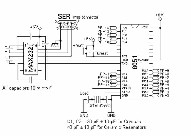
 up with dip sw input for testing. Here is the final schematic.

 The program places the pulse width digital data on the port and then
 toggles the /WR
 pin. Then the program triggers the 555 injector driver. That is all there
 is to it.
 Very little processor overhead and no software bugs:) No timer interrupts.
  You can
 think of this as a glorified 555 fuel injector system.

 One of these years microcomputer chips makers will build these in like
 they did with
  my latched priority interrupts :)


 Paul Lamar


OK, what are the DIP switches for?

I had already pinned up a 555 unit from the other info, and have considered
using that to test the engine. It worked with the CAS also, but I only ran
it long enough to see a spark.

I have looked over the MS code, and I agree that it is overly complicated
for our use, and I would venture to guess that it is for cars too.

I am going to try a simple formula instead of a table for the spark retard
while the turbo is running- crossing my fingers that a linear equation will
suffice. I am going to limit my wastegate to 8psi, and retard the timing
from 22 to 6 at anything above 10 inches MP.

I picked up a digital temp sensor from Sparkfun. It connects to the digital
input of my board, and broadcasts a unique serial number with the data.
This will allow me to use as many of these as I have digital input pins
for. The main benefit of this chip though is that it contains an Analog to
Digital processor already in it, so the output doesnt have to be processed
at all. And its waterproof. I will put this one in the intake to read
intake charge air temp. If this unit works well, I will place one in the
cooling system, and reading the air temp behind the radiator and maybe
other places.

Today I am preparing the stuff here for Hurricane Isaac, scheduled to pay
us a visit late Saturday. My fuselage is under the house, but my left wing
is sticking outside- and we all know that wings will fly whether the plane
wants to or not. 100 mph winds would be a bad thing at this point, so I get
to take the wings off the fuse for now. After Isaac prep is done, I can
start to map out the MAP sensor and begin to assemble the test system.

Kevin Alderman

Dip switches were just for static testing the DAC. Not needed on final board.
I found out my 8051 board does not support the USB in stand alone mode so I am just
using it a programmer. The working board will have an RS232 and I can always use a
RS232 to USB cable for dumping data at 9600 baud. There is lots of asm source code
around for that and the 8051 BASIC supports that as well. The data will spew out
constantly in the main back ground program. The PC terminal program can capture it to
a file on the hard disk.

Here is a preliminary lay out on the board. Its about 4" by 4" The hardware PWM is in
the upper right corner. The DAC is the 20 pin dip. Lower right is the MAP sensor.

BTW what works for ignition on this board is GM HEI module and any old coil you have
laying around. One HEI module per coil. Just like Megasquirt 1 Version 2.2. It is
triggered by the CAS hall effect sensor directly. Super simple :)

Paul Lamar

--
The Rotary Engine News Letter. Powered by Linux.
ACRE NL web site. http://www.rotaryeng.net
You Tube key word PaulLamar2
Copyright 1998-2012 All world wide rights reserved.