Paul,

 I understand you have started on your project. I did not want to
 intrude until I have time to read up and confirm some of the stuff on
 the MCU.

 Unlike a typical 8051/8052, the ATiny from Atmel has some disting
 advantages when used as a controller.

 I think we are in line in saying that we want to have one MCU per
 rotor, and a separate main one for all the other fancy functions, such
 as talking to the PC.

 The build in features are:

 1. Programmable pre-scaler up to 1024 counts on PWM and timer
 2. Pre-scaler reset to get accurate timing.
 3. Support TWI, a SPI compatible model, as a slave to talk to main
 MCU. Slave mode does not need CPU operations to function. Using this
 mode to communicate means that there is no need to dedicate a 16 bit
 timer as baud rate generator.
 4. 8 analogue channels, perfect for per rotor CHT and EGT monitoring

 In my mind, the main MCU calculates all the variants base on temp, air
 density, etc., and issue the necessary timing and fuel injection
 duration to the rotors via TWI. Each MCU then does one and only one
 thing, calculate the delay from a CAS signal, and generates a PWM
 generated pulse to energize the ignition coil.

 The rotor can also turn on injectors to measure the exact amount of
 fuel needed for the situation. Since it is doing nothing more than
 starting two delay circuits from CAS, where one delay is to get the
 proper coil turn on time, and the second delay is to get the time
 where EFI can be turned on. The programming is fairly simple and
 straight forward. With two counters and timers, I think it can be done
 with relative ease.

 We can setup a 10us timer, and then use software to count for the
 optimum time for coil and injection.

 I you are interested, I can help write up some of the code on this. I
 could try to use Basic but I am not sure how well it can do to control
 the various features.

 Henry


 On Sun, Aug 26, 2012 at 4:05 PM, rotaryeng <rotaryeng@earthlink.net wrote:
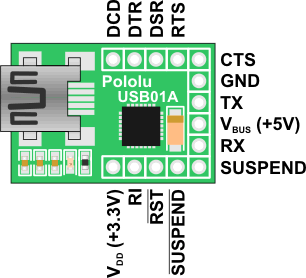
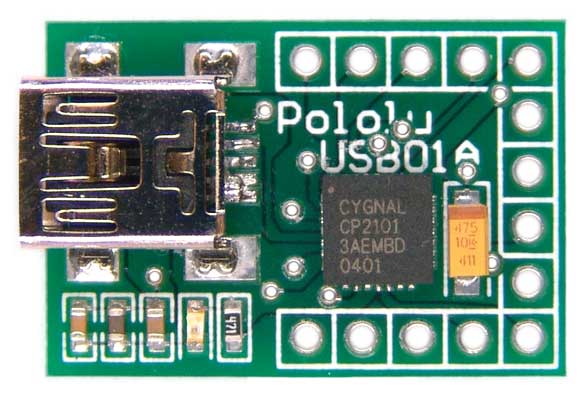
 I found this USB module that claims to work with all microcomputers so I ordered one.
 Some of the guys are using these with megasquirts.

 Kind of stupid putting a RS232 on there to generated a lot of weird voltages you
 don't need. The module only cost $15. I would probably have that in chips, caps and
 DB9 connector. It is shown in the lower right corner. The board is still 3.8 inches
 by 2.5 inches 3 for $50. The hardware PWM generator, injector drivers and FETs are on
 the right. The external 10 Mhz clock is the lower center. There is a divide by 1024
 chip that gets it down to below 10K for the RPM count. There is also a CD4049 that
 conditions the CAS for the 22 degree BTDC interrupt once per rev.

 The board is a cross between a bread board and a final design. I am going to
 experiment and find out what ports work for what.

 Paul Lamar

Here is an architecture drawing I am proposing.

Henry

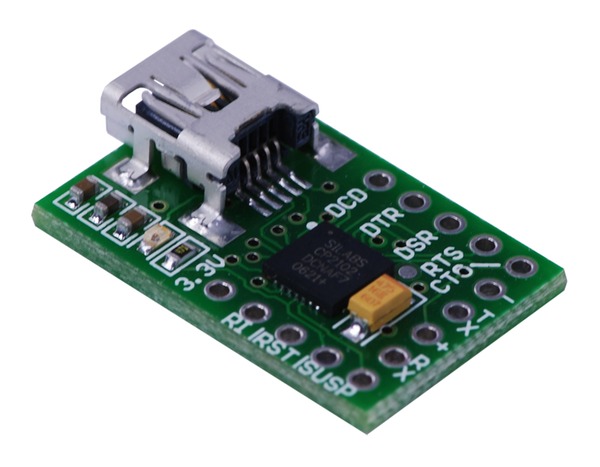
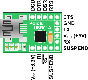
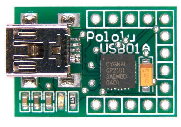
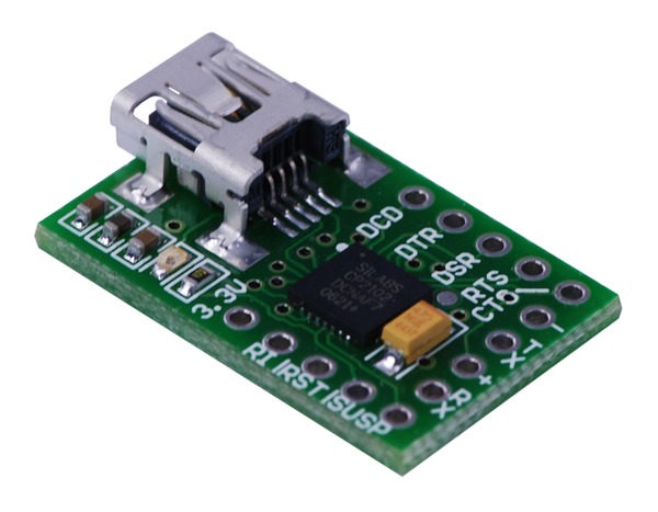
That's nice but here is the USB module that I put on my board. No RS232. This is
connected to Tx and Rx.

If you are in China you may not be getting all my messages.
Maybe NSA is censoring some of them.

Paul Lamar
--
The Rotary Engine News Letter. Powered by Linux.
ACRE NL web site. http://www.rotaryeng.net
You Tube key word PaulLamar2
Copyright 1998-2012 All world wide rights reserved.