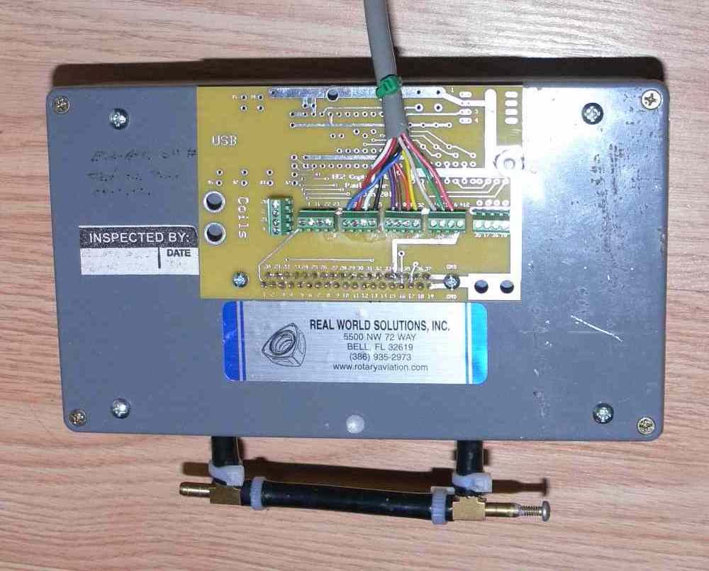
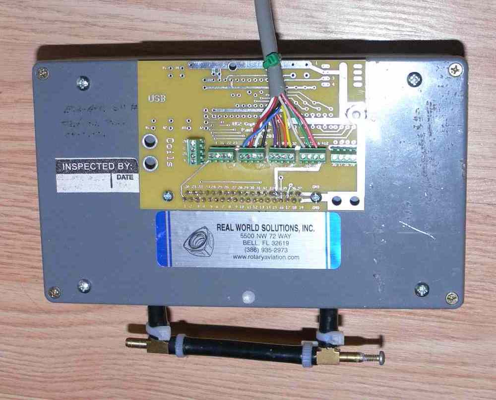
I found this USB module that claims to work with all microcomputers so I
 ordered one.  Some of the guys are using these with megasquirts.  Kind of
 stupid putting a RS232 on there to generated a lot of weird voltages you
 don't need.  The module only cost $15.  I would probably have that in chips,
 caps and DB9 connector.  It is shown in the lower right corner.  The board
 is still 3.8 inches by 2.5 inches 3 for $50.  The hardware PWM generator,
 injector drivers and FETs are on the right.  The external 10 Mhz clock is
 the lower center.  There is a divide by 1024 chip that gets it down to below
 10K for the RPM count.  There is also a CD4049 that conditions the CAS for
 the 22 degree BTDC interrupt once per rev.  The board is a cross between a
 bread board and a final design.  I am going to experiment and find out what
 ports work for what.

   Paul Lamar

  Paul,

  I understand you have started on your project. I did not want to
  intrude until I have time to read up and confirm some of the stuff on
  the MCU.

  Unlike a typical 8051/8052, the ATiny from Atmel has some disting
  advantages when used as a controller.

  I think we are in line in saying that we want to have one MCU per
  rotor, and a separate main one for all the other fancy functions,
   such as talking to the PC.

  The build in features are:

  1. Programmable pre-scaler up to 1024 counts on PWM and timer
  2. Pre-scaler reset to get accurate timing.
  3. Support TWI, a SPI compatible model, as a slave to talk to main
  MCU. Slave mode does not need CPU operations to function. Using this
  mode to communicate means that there is no need to dedicate a 16 bit
  timer as baud rate generator.
  4. 8 analogue channels, perfect for per rotor CHT and EGT monitoring

  In my mind, the main MCU calculates all the variants base on temp,
  air density, etc., and issue the necessary timing and fuel injection
  duration to the rotors via TWI. Each MCU then does one and only one
  thing, calculate the delay from a CAS signal, and generates a PWM
  generated pulse to energize the ignition coil.

  The rotor can also turn on injectors to measure the exact amount of
  fuel needed for the situation. Since it is doing nothing more than
  starting two delay circuits from CAS, where one delay is to get the
  proper coil turn on time, and the second delay is to get the time
  where EFI can be turned on. The programming is fairly simple and
  straight forward. With two counters and timers, I think it can be
  done with relative ease.

  We can setup a 10us timer, and then use software to count for the
  optimum time for coil and injection.

  I you are interested, I can help write up some of the code on this. I
  could try to use Basic but I am not sure how well it can do to
  control the various features.

  Henry

  I modified that a little bit. Each rotor module is also going to
  talk to the PC. That is a powerful feature that lets you send any
  parameter or the contents of any memory location  to the PC for
  debugging  purposes. Zbasic does that.

  I am not implementing coil on plug at this time. That will come later.

  2nd gen coils and any old coil with a GM HEI igniter will work. Just
  like megasquirt.

  My tach circuit is working well so I am not going to use the timers
  for RPM.

  Things are happening fast and I am going to start writing code in
  about 3 days when the proto board will be done.

  Paul Lamar


 I have used the upper left module to run a Ford. If you understand how they
 work, you can use almost any one on any engine. At the time, the Ford boxes
 were poor and crapped out. It did not help the engine had a LOT of crankshaft
 end play. It had an EEC2 California emission system. Hard to get information
 in Canada. Ran fine when I took out the worn 302 and put a 351 in. The major
 advantages of the 4 pin module are cost and availability as millions were made.

 Dale Davies


Paul,

What kind of tooth wheel set up would be required for what you have in mind?  I did a
major redesign and am using the 2nd gen RX 7 water pump so the the 3rd gen cover is
gone and I still can't use the 2nd gen CAS so I am going to have to mount a tooth
wheel to the front of the E shaft pulley and a sensor bracketed off the cover.  How
do you "clock" the wheel with respect to the E shaft?  I assume the sensor could be
any position around the perimeter as long as the TDC relationship between the sensor
and the wheel and the E shaft is maintained?  Plumbing is almost done.  I need to
rebuild the engine and provide EFI and it's done.Thanks for any help.

Joe Berki

Limo EZ

Well if your are going to use tooth wheels you'll need one wheel with one tit at 22
degrees BTDC and two CAS crank angle sensors spaced 180 degrees apart. One for the
front rotor and one for the rear rotor. In theory if one CAS or computer fails the
engine will run on one rotor.

Here is the latest one rotor PCB. All 8 channels of A to D are implemented, The
question is what to monitor and display? To give you a feel for the size of the board
it is the same as a break out board I did for Tracy's computer.

1.Here is a proposed list.
2.Mass air flow sensor. Not optional.
3.Tach signal. Not optional.
4.Intake air sensor. Optional.
5.Water temp.........Optional
6.Oil temp...........Optional
7.EGT................Optional
8.Oil temp out of the cooler.....Optional

The fuel flow is automatic and will be sent to the display as well as RPM and mass
airflow amount.

If you would like something else let me know now.


Paul Lamar

--
The Rotary Engine News Letter. Powered by Linux.
ACRE NL web site. http://www.rotaryeng.net
You Tube key word PaulLamar2
Copyright 1998-2012 All world wide rights reserved.