Paul,

  I looked at the information on the web about TDC and how the E
  shaft pulley is marked at 5 degrees and 20 degrees BTDC and
  has a unique hole pattern  to ensure one position
  installation.  It was also stated the when the keyway is at
  the 9:00 position the E shaft is at TDC.

  From that I can make the 2 tit tooth wheel.  2 sensors 180
  degrees apart will provide the signal for ignition and I
  assume you are going to use that for initiation of firing an
  injector?  Do we need another wheel for the tach signal?

  Are you are using MAF and tach to determine injector pulse
  width?

  The system will be 3 boards one on each rotor with the 8 A to
  D channels used.  The third board provides the interface to
  the PC.  Could you use the optional channels from both rotor
  PCBs to increase the  different types of data to display?
  Just trying to keep up with the design.  Thanks

  Joe Berki
  Limo EZ

 You won't need three boards. There will be one USB port board per board so at
 the
 moment you can get data from only one rotor at a time. As we go along that may
 change.

 I'll know more after I get the software working.

 I am focused on BASCOM right now. It's free for small projects and the IDE looks
 simpler to use than the Mikro IDE. I have the demo program for both. BASCOM is
 half
 the price of Mikro if I decide to buy the full blown versions.

 Paul Lamar

Paul,

The intake tubes came back from the welder and they fit perfectly.  Are you going to
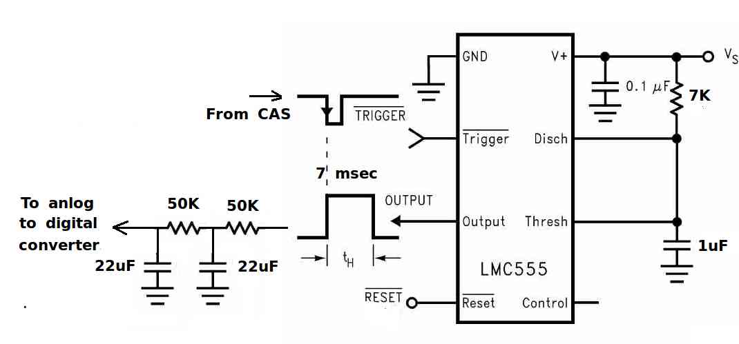
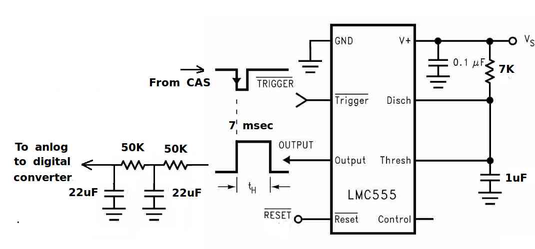
use your analog tach circuit?  It uses the CAS to trigger will that require an
additional wheel  to the 2 tooth wheel?  I will start on modifying the plenum for the
MAF sensor and make it removable.  Thanks

Joe Berki
Limo EZ

I am going to try it out soon. The PC boards are due in next week. BTW one can buy
all sorts of digital volt meters that can read the tach for a RPM read out on the
dash. Since 5 volts is 8000 RPM you want to use a voltage divider to get the input to
the volt meter down in the range of 0 to 1 volt giving a 3 digit read out of 0 to
10,000 RPM.

.8V * X =  5V
X = 5/.8 = 6.25 : 1

Lets say the big resister is 62.5K and the little resistor is 10K.
I can put the voltage divider on the PC board with a connection pin for the
voltmeter. Simple solution for a tach read out on the panel.


The 8051 is  von Neumann architecture where the CPU can be either reading an
instruction or reading/writing data from/to the memory.  Like the 6502 used in the
Apple II  and 6800 used in the megasquirt.  It has a complex instruction set. That
means the instructions are powerful and do a lot compared to RISC instruction that do
only one simple thing. IMHO complex instruction computers  are fun to program in asm.
 RISC computer instructions are  tedious to program in asm. That is why they mostly
use high level language to program RISC computers The PIC is Harvard architecture
RISC computer architecture with physically separate storage and signal pathways for
instructions and data.

The 8051 has been around for 40 years and remains very popular. There is a 8051 in
the keyboard you are typing on.  Unfortunately the 6502 is long gone.

BTW I just got a copy of "The 8051/8052 Microcontroller" by Craig Steiner 2005.
Excellent book for asm programming. 331 pages. VERY comprehensive. The bible of asm
8051. Well worth the $60.


Paul Lamar


--
The Rotary Engine News Letter. Powered by Linux.
ACRE NL web site. http://www.rotaryeng.net
You Tube key word PaulLamar2
Copyright 1998-2012 All world wide rights reserved.