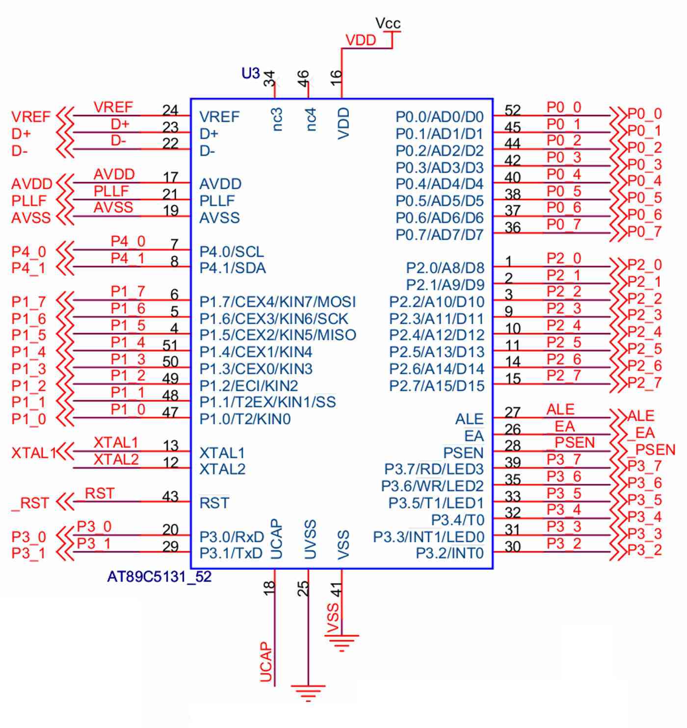
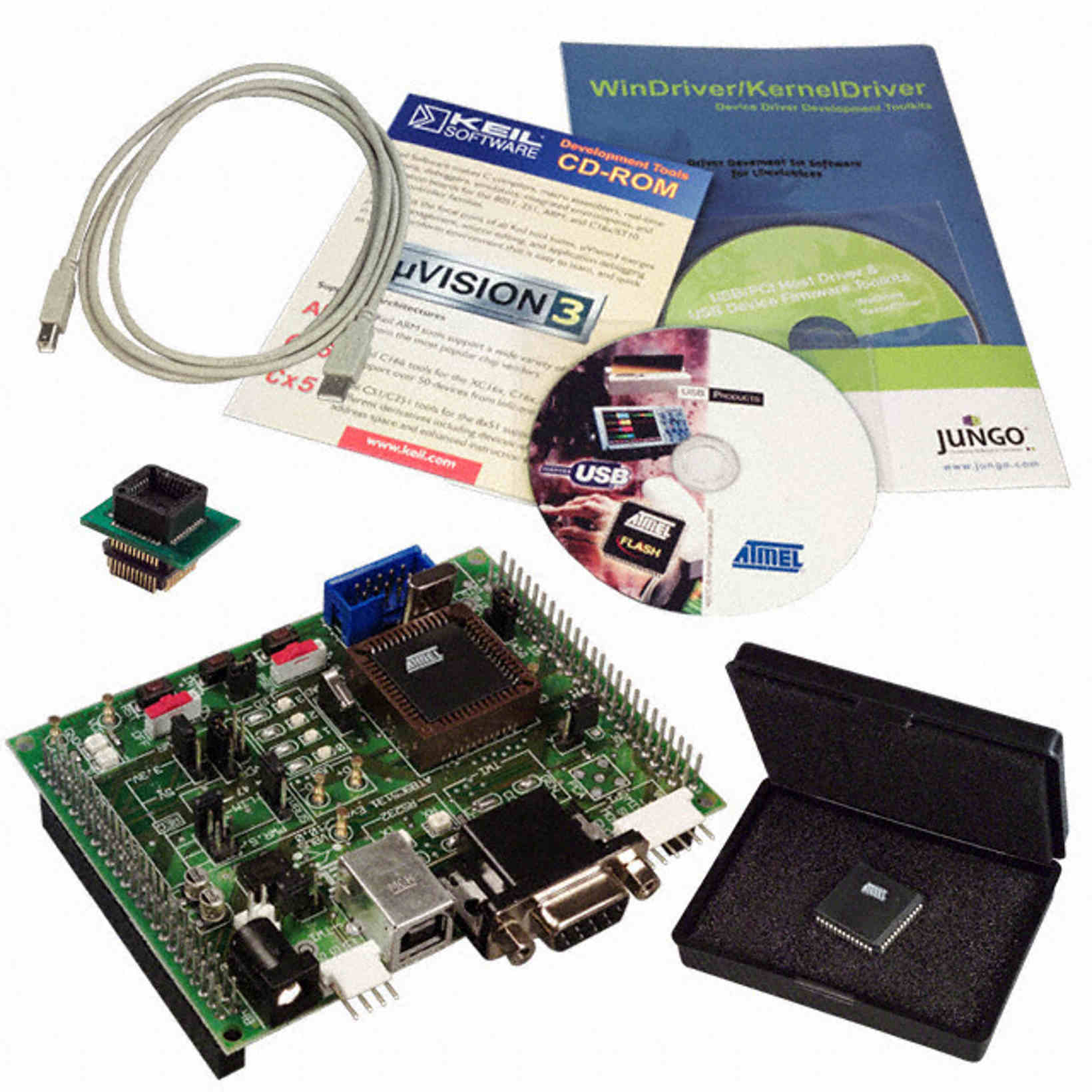
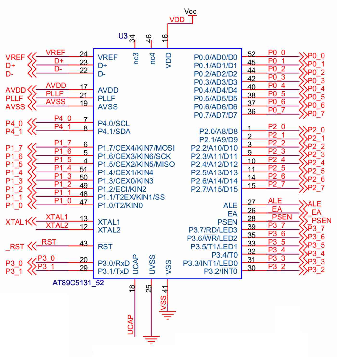
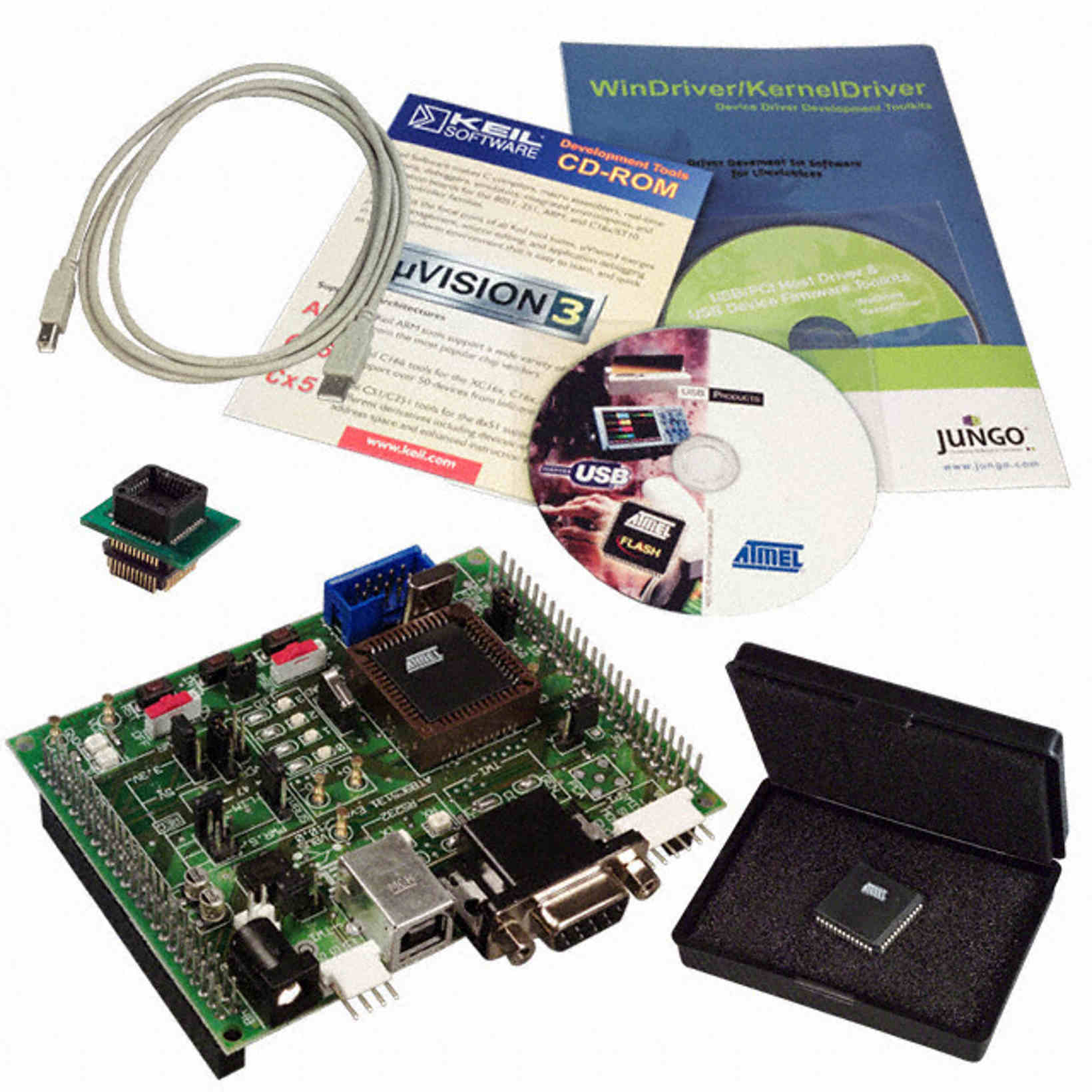
It executed it's first program. Had a wiring error but it can be
fixed with
jumpers.
The silver lever is a Aries zero insertion force socket for getting
the chip
in and
out quickly for programming purposes. There is no on board in circuit
programming
for this version. You must have a stand alone programmer.
It is not fully populated yet but all the other circuits have been
tested on
the bench.
Paul Lamar
NICE !
Barron
I am thinking of going one step up on processors to the 80C51.
It is at least four times faster than the 8051. It has built in USB
and PWM mode for the timers.
BTW I am up in Monterey for the rotary races. Mazda owns the race
track. We flew in to San Francisco which was a big mistake, You have
to take a train to get a rental car. The people up here are logic
and reason challenged. They could have built a big parking garage
for the rental cars cheaper than the train. Total travel time was
six hours. I could have driven it in 4 and the cost would be much
much cheaper if you need to pay for airline tickets even with gas at
$4 in CA. We don't as Robin is a retired UAL A&P. The Comfort Inn
has lousy Internet service. I am at Denny's.
My dad had a bad experience flying standby- he flew from Charlotte to
Chicago and was trying to get back. Took 2 days for him to get a seat.
Seems like Chicago might be a tad busy.
I have my board up and running too. I set it up with staged injectors
and manual leaning, all of which seem to be working correctly. I read
MAP, temp and RPM. I used a second board as a signal generator, and it
worked well up to 6000 rpm where the generated pulse width was short
enough that it was having trouble reaching the threshold voltage to fire
the coils. I think that I may have to use a second chip like the 555 as
a trigger for the coil to make sure it works at high rpm. At low rpm the
CAS will trigger the board, but didn't reliably fire the coils. It did
fine at high speed.
It will be a bit before I can test it on the engine, I still have to fab
intake, install the radiators, etc. I did finally finish the left wing
except for installing the tip! Progress, little by little.
I will keep testing the code and the board and see how it holds up.
Paul, how many kb is your code file? Mine came in just under 10k total
uploaded to the board including the libraries for the digital temp chip.
The executed code is around 5k, the temp sensor I used has a built in
ADC, so it outputs the temp digitally.
Kevin Alderman
I don't know yet. My BASIC compiler is due to be delivered on Monday.
So far I have been running the blink program.
The 80C52 has 32K flash to work with. I am not using the in circuit
programming feature. I am using the starter kit to program the chip and
move it to the EFI board. That keeps down the size of the EFI board to
about 2.5" by 3.8".
Features
• 80C52X2 Core (6 Clocks per Instruction)
– Maximum Core Frequency 48 MHz in X1 Mode, 24MHz in X2 Mode
– Dual Data Pointer
– Full-duplex Enhanced UART (EUART)
– Three 16-bit Timer/Counters: T0, T1 and T2 with PWM
– 256 Bytes of Scratchpad RAM
32-Kbyte On-chip Flash In-System Programming through USB or UART
4-Kbyte EEPROM for Boot (3-Kbyte) and Data (1-Kbyte)
On-chip Expanded RAM (ERAM): 1024 Bytes
USB 1.1 and 2.0 Full Speed Compliant Module with Interrupt on Transfer
Completion
– Endpoint 0 for Control Transfers: 32-byte FIFO
– 6 Programmable Endpoints with In or Out Directions and with Bulk,
Interrupt or
Isochronous Transfers
• Endpoint 1, 2, 3: 32-byte FIFO
• Endpoint 4, 5: 2 x 64-byte FIFO with Double Buffering (Ping-pong Mode)
• Endpoint 6: 2 x 512-byte FIFO with Double Buffering (Ping-pong Mode)
– Suspend/Resume Interrupts
– Power-on Reset and USB Bus Reset
– 48 MHz DPLL for Full-speed Bus Operation
– USB Bus Disconnection on Microcontroller Request
5 Channels Programmable Counter Array (PCA) with 16-bit Counter, High-speed
Output, Compare/Capture, PWM and Watchdog Timer Capabilities
Programmable Hardware Watchdog Timer (One-time Enabled with Reset-out):
50 ms to
6s at 4 MHz
Keyboard Interrupt Interface on Port P1 (8 Bits)
TWI (Two Wire Interface) 400Kbit/s
SPI Interface (Master/Slave Mode)
34 I/O Pins
4 Direct-drive LED Outputs with Programmable Current Sources: 2-6-10 mA
Typical
4-level Priority Interrupt System (11 sources)
Idle and Power-down Modes
0 to 32 MHz On-chip Oscillator with Analog PLL for 48 MHz Synthesis
Low Power Voltage Range
– 3.0V to 3.6V
– 30 mA Max Operating Current (at 40 MHz)
– 100 μA Max Power-down Current
Industrial Temperature Range
Packages: PLCC52
Description
AT89C5131 is a high-performance Flash version of the 80C51 single-chip
8-bit micro-controllers with full speed USB functions.
AT89C5131 features a full-speed USB module compatible with the USB
specifications Version 1.1 and 2.0. This module integrates the USB
transceivers with a 3.3V voltageregulator and the Serial Interface
Engine (SIE) with Digital Phase
Locked Loop and 48 MHz clock recovery. USB Event detection logic (Reset
and Suspend/Resume) and FIFO buffers supporting the mandatory control
Endpoint (EP0) and up to 6 versatile Endpoints (EP1/EP2/EP3/EP4/EP5/EP6)
with minimum software overhead are also part of the USB module.
AT89C5131 retains the features of the Atmel 80C52 with extended Flash
capacity (32-Kbyte), 256 bytes of internal RAM, a 4-level interrupt
system, two 16-bit timer/counters (T0/T1), a full duplex enhanced UART
(EUART) and an on-chip oscillator.
In addition, AT89C5131 has an on-chip expanded RAM of 1024 bytes (ERAM),
a dual-data pointer, a 16-bit up/down Timer (T2), a Programmable Counter
Array (PCA), up to
4 programmable LED current sources, a programmable hardware watchdog and
a power-on reset.
AT89C5131 has two software-selectable modes of reduced activity for
further reduction in power consumption. In the idle mode the CPU is
frozen while the timers, the serial ports and the interrupt system are
still operating. In the power-down mode the RAM is saved, the peripheral
clock is frozen, but the device has full wake-up capability through USB
events or external interrupts.
Paul Lamar
--The Rotary Engine News Letter. Powered by Linux.
ACRE NL web site.
http://www.rotaryeng.net
You Tube key word PaulLamar2
Copyright 1998-2012 All world wide rights reserved.