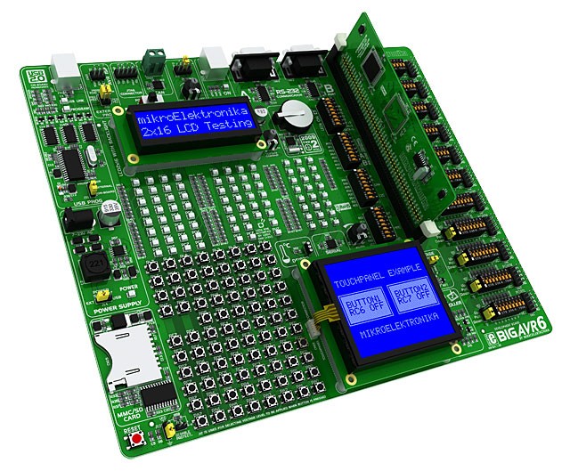
It executed it's first program. Had a wiring error but it can be fixed
   with
    jumpers.

    The silver lever is a Aries zero insertion force socket for getting the
    chip
    in and
    out quickly for programming purposes. There is no on board in circuit
    programming
    for this version. You must have a stand alone programmer.

    It is not fully populated yet but all the other circuits have been tested
    on
    the bench.

    Paul Lamar

    NICE !

    Barron

    I am thinking of going one step up on processors to the 80C51.
    It is at least four times faster than the 8051. It has built in USB and
    PWM mode for the timers.

    BTW I am up in Monterey for the rotary races. Mazda owns the race track.
    We flew in to San Francisco which was a big mistake, You have to take a
    train to get a rental car. The people up here are logic and reason
    challenged. They could have built a big parking garage for the rental
  cars
    cheaper than the train. Total travel time was six hours. I could have
    driven it in 4 and the cost would be much much cheaper if you need to pay
    for airline tickets even with gas at $4 in CA. We don't as Robin is a
    retired UAL A&P.   The Comfort Inn has lousy Internet service. I am at
    Denny's.


   My dad had a bad experience flying standby- he flew from Charlotte to
   Chicago and was trying to get back. Took 2 days for him to get a seat.
   Seems like Chicago might be a tad busy.

   I have my board up and running too. I set it up with staged injectors and
   manual leaning, all of which seem to be working correctly. I read MAP,
  temp
   and RPM. I used a second board as a signal generator, and it worked well
  up
   to 6000 rpm where the generated pulse width was short enough that it was
   having trouble reaching the threshold voltage to fire the coils. I think
   that I may have to use a second chip like the 555 as a trigger for the
  coil
   to make sure it works at high rpm. At low rpm the CAS will trigger the
   board, but didn't reliably fire the coils. It did fine at high speed.

   It will be a bit before I can test it on the engine, I still have to fab
   intake, install the radiators, etc. I did finally finish the left wing
   except for installing the tip! Progress, little by little.
   I will keep testing the code and the board and see how it holds up.

   Paul, how many kb is your code file? Mine came in just under 10k total
   uploaded to the board including the libraries for the digital temp chip.
   The executed code is around 5k, the temp sensor I used has a built in ADC,
   so it outputs the temp digitally.

   Kevin Alderman

   Kevin, What AT chip number are you using? ZBASIC uses the AT1280 and the
   AT1281.
   A lot of the problems with the timers are the same. Are you using software
   PWM?
   I am moving much faster with ZBASIC than MikroBASIC and the 80x51xx.
   Mainly because the help is in my time zone and not half way around the
   world :)

   Paul Lamar

   My board has the Atmega 2560 chip.
  http://arduino.cc/en/Main/ArduinoBoardADK.  Says that at 5.5 volts, it
  will
  execute 16 million instructions per second, 1 MIPS per Mhz, and it runs at
  16Mhz.

  The preliminary run showed it worked as planned. The only issue I had at
  all was the signal generator board. I tried to simulate the input from the
  CAS at 8000 RPM. I used the analog output of the Arduino Uno as the signal,
  but the analog output is in the form of a PWM. When I "fired" the signal
  generator at 9 usecs or less, the resulting voltage from the uno wasn't
  sufficient to fire the coil. I tried it through a transistor that would
  trigger at .7 volts, and it worked but had a delay that might make it
  problematic at high RPMs. Need more testing. I have a high speed lathe that
  I can stick the CAS in and turn it at 4000 RPM, and as we know the CAS
  turns at half engine speed. Should simulate 8000 rpm effectively. I have
  been working on my wings, avionics, etc. and trying to program an
  electronic health database engine along with about a dozen other projects,
  so I haven't gotten back to it- yet.

  I programmed the Mega to read temp, MAP and RPM (which doesn't calculate
  right at the moment) and come up with a pulse width. This is modified by
  the analog input of a POT, with 3 volts being 1.00 and adjusting up or down
  from there. I have my injectors staged with primary and secondary depending
  on the pulse width. The ADC PWM uses 255 as max, so when injector 1 gets a
  PWM over 255, injector 2 gets the remainder. That would be 100 percent duty
  cycle, so I might reduce that to 200. I'll see how it goes.

  Kevin Alderman

  What is that injector width in ms? I think you will have interrupt
  conflicts at 7000
  RPM using the built in software PWM. As I understand it the PWM soft ware
  disables
  all other interrupts while it generates pulse widths. Same for RPM if you
  are using a
  timer. I did those two functions in hardware to avoid the interrupt
  conflict problem.
  You may not notice it if you trigger the 2nd gen ignition directly from
  the 2nd gen
  CAS. You will need an amp for that. A CD4050 or CD4049 CMOS chip will do a
  wonderful
  job if you use 3 or more gates wired in parallel.

  BTW it won't work with coil on plug for those using the LS1 or RX8 coils
  so don't
  even think about it :) Kevin is using the 2nd gen coils which in essence
  are the same
  old coils from 50 years ago but have an igniter.

  The 1260 chip is basically the same as the 1281 (128K flash 64 pin) ZBASIC
  uses but
  the 1260 has more flash memory. 256K flash instead. I think you mentioned
  you are
  only using 10K. Both run at 16 MHZ. I have the ZBASIC 1280 100 pin with
  125K flash
  board but the I/O is a bit overkill. I scaled back to the ZBASIC 1281
  board 64 pin. A
  bit cheaper at $80 rather than $100. Not including the EFI specific hard
  ware.

  Paul Lamar

 Kevin, you might want to use a high speed buffer. F series buffers are
 fast. Off my head I remember having good result with 74F245 and the swith
 on ns level. Those are 5 volt parts. I assume.the coil trigers on 5V.

 Henry Nee

 I am considering a new strategy of using polling instead of an external interrupt
 when the CAS cames in. The trouble with the interrupt is the computer may be in the
 midst of sending some COM data to the tablet when it comes in. When the interrupt
 service routine is finished it goes back to the COM program where it left off. That
 could result in garbled characters.

 If I latch the CAS pulse and sit in a back ground loop watching for the CAS and then
 do what needs to be done I needn't worry about garbled characters. The down side is I
 have only 8 milliseconds at 7000 RPM to get everything done before I need to go back
 and watch for the CAS again. Since the COM baud (bit) rate is roughly 115,000 per
 second and a character is around 10 bits  that is 11,500 characters per second.  8
 milli seconds is .008 seconds. That means I can only send about 90 characters max to
 the tablet per engine rev. The characters would be coming in to the tablet  at the
 rate of 8000 x 90 /60 or 12,000 characters per second. That assumes I do nothing else
 except send data to the tablet. In the real world my guess it would be half that
 rate. Do other things for 4 milliseconds and send characters for the last 4
 milliseconds. Send only 45 at a time. Then go wait for the next CAS pulse.

 At 3500 RPM the computer would be wasting 50% of the time available to it.
 That might be OK. The ZBASIC AVR computer is very fast. I could also read the RPM the
 moment the CAS came in and do different programs that send out characters depending
 on the RPM. At 3500 RPM and below I would have 16 milliseconds or more to work with.
 This strategy is the sledge hammer approach but it is safe and you don't have to
 worry about two or more random and asynchronous interrupts coming in at the same time
 and conflicting.


 Paul Lamar

Paul,

That's why I initially contemplated a dedicated MCU per rotor, and
then uses SPI or I2C to talk to a main MCU, and then the main MCU can
talk to the tablet.

>From experience, I figure that I would not have enough time to do all
the things I need done at high RPM. (I am thinking support of up to
15,000 rpm, as you mentioned it as a possible limit when using light
weight rotors.)

With SPI, the data rate will be in Mega Bits, not Kilo Bits. Also
there is usually dedicated circuit for communication. (Avoid any MCU
that requires the use of software to manage asks of every single byte
to reduce interrupt collisions)

We can use a more powerful main MCU to talk to the tablet. In my mind,
everything will be interrupt driven, with priority given to CAS
capture. Lost bytes to or from the tablet can be detected and
recovered via re-transmission.

Henry

You are always way ahead of me Henry. I am not kidding or being sarcastic. You really
are. I agree. SPI or I2C would be a lot faster than a USART.

In the mean time I'll try to get get this Zbasic 1281n board going with a little help
from the hardware to off load as many interrupts as I can. I'll see how it goes.

Can you come up with a cheap  slave chip to do the com. Mikro has a edge connector
card with a 100 pin AVR 1260 for $21 but they are temporarily sold out. It is about
3.5 to 4 inches long. They do superb workmanship on the hardware. The support is only
so so. It cost more ($25) to ship it from Zagreb in Croatia.

BTW The more I learn about the ZBasic BASIC the better I like it. Mikro AVR BASIC Pro
is about the same but it does a better job of handling external interrupts.

Here is a summary pdf of Zbasic.

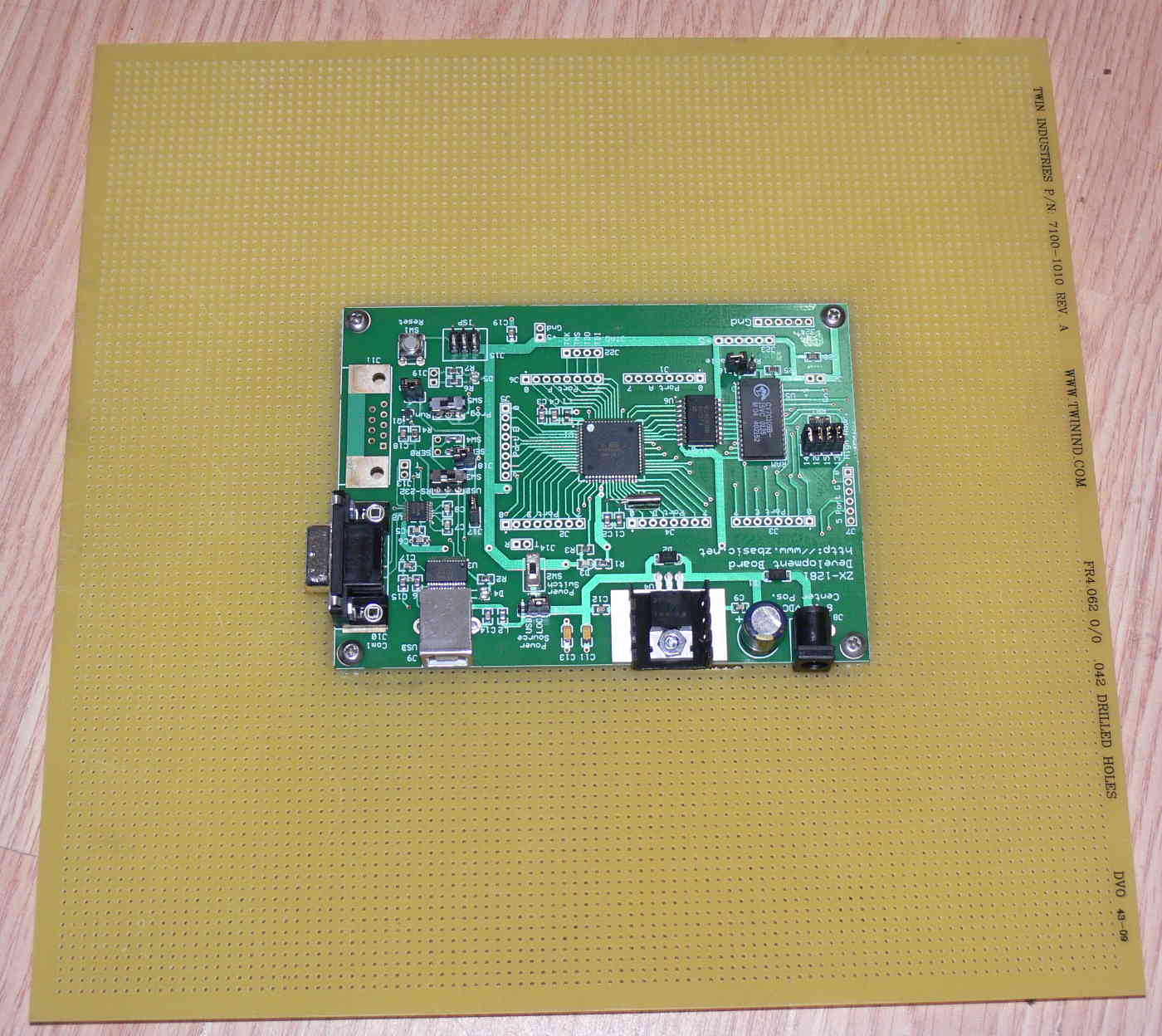
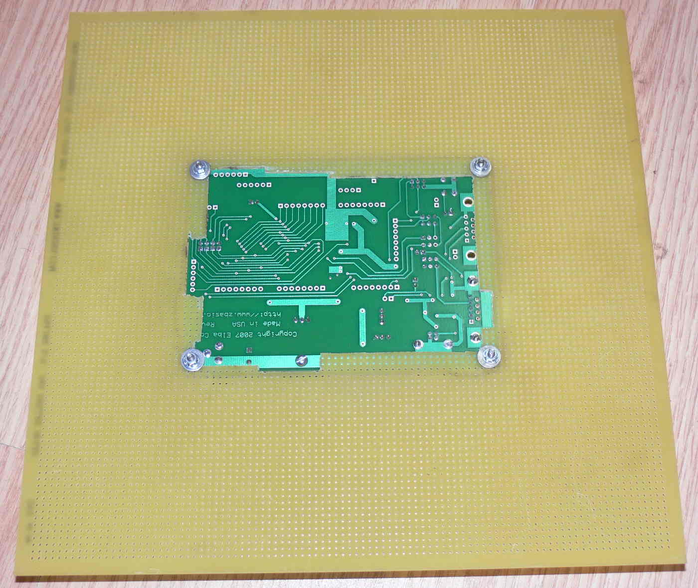
Here are some pictures of my wire wrap proto board to try a few hardware ideas out.
I just got the 1281n board today so the wire wrap pins are not soldered to the mother
board yet.

Paul Lamar


--
The Rotary Engine News Letter. Powered by Linux.
ACRE NL web site. http://www.rotaryeng.net
You Tube key word PaulLamar2
Copyright 1998-2012 All world wide rights reserved.