I have a question regarding the stock Mazda oil cooler and cabin heat-

 Can I get enough heat from the oil cooler to duct some into the cabin for
 passengers and defog/ defrost? I have room at the back of the engine
 compartment to mount the oil cooler, and I have the metal adjustable ducts
 from my viking where the muffler heat came in. I have a heater core and was
 going to mount it behind the panel, but this seems to be simpler if I can
 get enough heat from it.

 With the metal duct pieces, I can regulate the heat with a cable, or I can
 use the servo motors that came with the RX8 heater core assembly. Either
 way, simple is better.

 Kevin Alderman

 One third of the total cooling comes from the oil. The stock 2nd RX7 gen
 oil cooler
 is very effective for its size.

 I don't know about a Wheeler express. That is a fairly large cabin. Perry
 Mick tried
 that for awhile on his long easy but he did away with it eventually. I
 don't know
 what his reasoning was. The device is below the cockpit.

 Back near the firewall is a tricky place to put the oil cooler from a
 ducting
 standpoint however it has been done before and it worked.

 I think it is worth a try if you can duct the exit in such a fashion as to
 not hurt
 the cooling when you don't need the cabin heat. It is best to mount it
 flat in that
 position so there is a 3 or 4 inch long strait section of exit duct after
 the core.
 Any curvature near the core will restrict the flow.

 If you send me some dimensions of the hard points on the firewall and a
 rough out
 line I can do a better more accurate 3D. A 3D will save you a year of
 starting over
 two or three times. Typical for people trying to do it the old fashion
 trial  and
 error method.

 It is best to use as large a spinner as you can with rotaries as they are
 basically
 round engines.

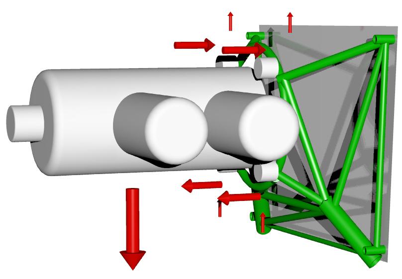
 This is a Wheeler Express with a 3 rotor but I am not sure about how
 accurate the
 dimensions are.

 Paul Lamar


Where it is in the photo is where it would need to go, that is above the
rudder tubing and linkages and I can duct it around the radio stack that
goes in the middle.  The other alternative is to use the heater core that I
have. I already made the fiberglass ductwork to mount the heater core under
the panel, but I dont think I want a potential water source that close to
my avionics. But, I prefer not to make a big hole in the firewall either.

The air source would be a NACA scoop on the lower cowl section with SCAT
hose bringing air in from both sides to the cooler. I will need to do that
anyway for cooling and then dump the air out the bottom. I have the dampers
and ducting that came with the Viking that diverted air from the muffler
cuff into the cabin or overboard.

If 1/3 of the heat is dissipated through the oil cooler, I assume that the
other 2/3rds is divided up between water and exhaust. So, there should be a
relatively equal amount of heat available from either source. I will be
using a turbo, so an exhaust cuff would be problematic, so I am back to
water and oil coolers. I have pondered 2 heater cores one under the panel,
and one behind the back seats. I can add a NACA scoop behind the rear seats
to provide air or I have a couple of small squirrel cage fans that can
provide air movement. Might go the fan route so that I can control fan
speed and therefore the amount of heat.

I saw an ad for the new diesel 182 in AOPA that had a heat exchanger
mounted on the firewall and the air ducted through the firewall to the
cabin. Might make installation a bit easier, just a little ductwork under
the panel instead of a heater core, valve and ducting.

Looking for ideas, like you said a few minutes of planning saves months of
work and re-work.

Kevin Alderman

Send me all that stuff and I can put it in the 3D. No cost. Free!!

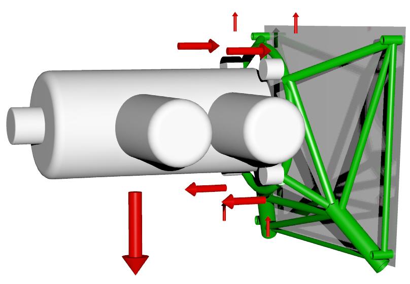
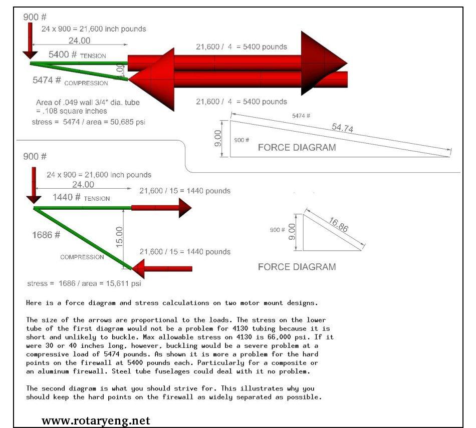
I was surprised they put the MM hard points so far in from the skin. That makes the
firewall a good speaker cone for transmitting engine vibration to the cockpit
in the form of sound waves. If it was mine I would move the hard points up and  out
towards the skin. Now is the time to do it. They did that so they could save money by
using an off the shelf Cont. motor mount.

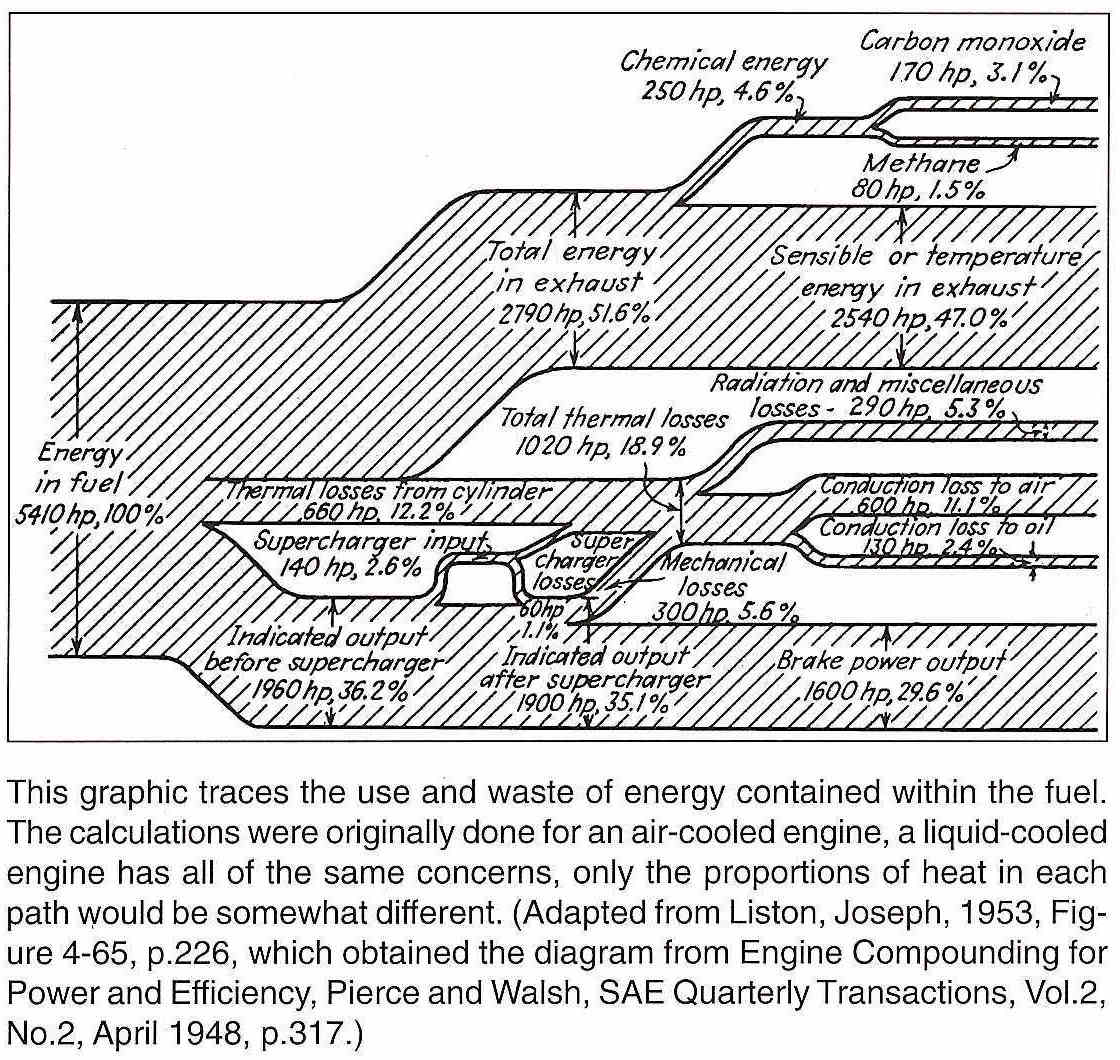
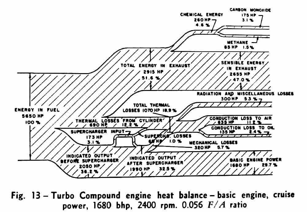
Here is the gallon of gas total heat balance for most IC engines. 30% out in net HP.
50% out in the exhaust. 20% for the cooling system. In the case of the rotary 13% for
the water rad and 7% for the oil cooler. The rotary is a not quite that good with 28%
net HP out. The 50% in the exhaust is why turbo compound works so well.

NACA scoops don't work in applications where there is significant resistance to the
internal air flow. Try to use the stock cowl openings or put a vertical opening scoop
on the bottom of the cowl. They see slip stream full dynamic pressure. You will see
this in my book.

Paul Lamar


--
The Rotary Engine News Letter. Powered by Linux.
ACRE NL web site. http://www.rotaryeng.net
You Tube key word PaulLamar2
Copyright 1998-2012 All world wide rights reserved.