Hi All, It?s been a while since I?ve been on the newsletter
 betweenwork and trying to make progress on the Long EZ.
 Anyway, it?stimefor the Fuel system and I wanted to get
 feedback from thegroup onmy design. I attached a PDF of my
 concept whichutilizes 2different sumps, 1 rear cockpit
 thigh support/fuelsump and a 2ndsump in the hell Hole. The
 reason for the addedsumps is to try torecover some of the
 fuel I will be losingdue to installing Infinityretractable
 gear.Anyway, myassumption was a P-Ported 13B with aTO4
 turbo so the linesneed to be able to keep that thirsty puppy
 humming at WOT. Iguess it would make about 350hp at WOT. Anyway,
 can you guystake a look and shoot holes and make
 recommendations. I lookat the fuel system and Engine
 installation design as themostcritical systems we develop
 so I want it to be right.

 Thanks

 Mike C.

 I'd put a fuel drain in the lowest part of each sump where lowest
 iswhen the ship is parked.

 I'd put the pumps in the last sump.

 I don't see provision for fuel return.

 tc

 --
 Thanks TC, cant believe I forgot the return line. I decided to do
 away with the Hell hole sump, seems like I would be creating a lot
 of work for little gain. I did add a fitting to the thigh sump
 so Icould add an Aux Tank if it was ever needed. Could just
 strap itinto the GIB seat. Anyway, I have a couple of questions
 about thefuel return. Will it have enough pressure to overcome
 the headpressure in the sumps from the Strake tanks? And the
 thigh sump isprobably only 2-3 Gallons so should I be worried
 about hot fuel inthe sump? Or should I just return the fuel to
 the strakes? If Ireturn it to the strakes is there a chance I
 could empty the sumpfaster than the gravity fill line can return
 it to the sump? Thanksagain for all the help guys. I attached
 an updated diagram, throw arrows!

 Mike C.

 Paul
 I'm resending this because I never saw it posted, Might
 have gotten lost in the ether.

 Thanks

 Mike C.

 Now you are talking my language as an instrument tech (industrial)
 . Why use cad plated carbon steel fittings. This is designated by
 the single S prefix. I would use either SS (stainless) there is a a
 couple of different stainless types available or alloy. Also a
 couple of options. Use the SS ferrule sets. With time the cadmium
 plating seems to let the nut stick to the fitting and it takes some
 effort to break it loose. SS does not have the same problem. Its
 problem lies with a lack of tolerance to cross threading. Proper
 tightening of the fittings is important. Start with the nut just
 finger tight on the fitting and then tighten 1 1/4 turns. Use a felt
 pen to mark it to get it right.Also, I would use 1/2" return line
 to make sure there is no restriction there.What is the method of
 connecting to the sumps. You show tube unions
 (600-6) with the tube coming out of the sump. Another fitting
 available is SS-6-TA-1-? i Left a question mark for the pipe thread
 size; 1/4,3/8, or 1/2"NPT. These would be 4, 6, or 8 like AN
 designations. This would then allow the use of the tube unions
 directly. A better option is SS-600-1-? tube adapter. If you need a
 90* then SS-600-2-?. There is also 45* available. This would
 eliminate a possible leak source or two. You know every joint will
 leak eventually.Swagelok has available a small catalogue that is
 about 6" x 3" and about 3/8" thick that lists a lot of this and
 explains the codes for it's fittings. Also pressure ratings for
 tubing sizes and materials.

 Dale

 Hi Dale
 Thanks for the info, I only chose the Steel because they were a
 lot cheaper, I'll change to SS. I will also increase the size of
 the return line to 1/2". My plan is to use Al tubing which will be
 floxed into the sumps and Swagelok fittings to connect the lines toe
 the stub tubes in the sump. It seemed like a simple solution. I
 did look at the Swagelok fittings with NTP -600-2 on one end but
 thought if I used Al tubing I could bend the tubes in the sump to
 the location (lowest point for the fuel feed and highest point for
 the fuel supply and vent) that they needed to be at. Then flox them
 in place through the sump walls with a stub tub protruding which
 will allow me to use a union to attach to the rest of the supply
 lines and vents. Now that I think about it I could use a ss-600-2-8
 for the return lines and a SS-600-2-12 for the Sump feed and
 increase the feed line size to 3/4". Then use the original plan for
 the fuel pick up lines to the Andair valve.Keep shooting arrows,
 I really want a bullet proof Fuel System. No fuel = no thrust = BAD
 DAY!

 Thanks

 Mike C.


 Hi Mike,

 Another option for the lines instead of floxing them is to put a
 pipe fitting into the tank as required. You can get bore through
 fittings from Swagelok. These do not have the smaller bore down from
 the nut and ferrule area that stops the tube from going farther
 through. If you put a 3/4" NPT fitting in the tank, you can put a
 suction screen on a tube and have the tube bent to where you need
 the end at. Then you slip the fitting over the tube and tighten the
 fitting in. Once the fitting(tube adapter in Swagelok speak) is
 tight, you tighten the tube nut to lock the tube in place. Then you
 can cut the tube off an inch from the nut and can then use a tube
 union to connect to it. There is also available reducing unions. An
 example of the part number for these is; SS-810-6-6. This would
 connect a 3/8" tube to a 1/2" tube.

 Also there is Alloy fittings for different applications to deal with
 some chemicals. Some of these may be lighter, but also more costly.
 Once you finalize the fittings required you can contact the local
 Swagelok people and compare the costs. I do not think the weight
 savings would be a lot, but a kitchen scale would answer that quickly.

 The fitting to put in the tanks are readily available for welding
 into pipe or thin wall tanks made of sheet metal. Known as weld-o-
 let. To flox, protect the threads and use a course sand blast to
 rough up the surface. Fiberglass tanks use this method and have 2"
 to 4" fittings with no problem. Grounding cables are commonly
 attached here also as a stud can be welded to the fitting before
 glassing that the ground can be attached on to. Very common in the
 oil patch for produced tanks to catch water. Of course there is
 always some hydrocarbons with the water that could ignite with a
 static build up.

 Dale Davies

 Hi Dale
 Attached is the diagram for an Aluminum Sump, Can you check out the
 fittings I identified to make sure they make sense? I thought a lot
 about it and I think Al is the right way to go for the Sump. I can
 just cut out the parts and have them all welded together and have
 the fittings welded on which will eliminate a possible leak source.
 It also solves any grounding issues.

 Thanks

 Mike C.


 Hi Mike,

 The fittings you specify are 90* weld in of Al construction. OK. The
 A-1210-C should be changed to A-1210-P as the fitting is configured for
 a nut and ferrule. The -C is to cap a tube that has a nut and ferrule on
 the end of it.
 Next to consider is the flow capabilities. Straight or 90* fittings are
 drilled to the same diameter, BUT the 90* introduces turbulence and thus
 a restriction to flow. The fittings are drilled to a slightly smaller
 diameter than the tube ID of the lightest tube wall available. A tube
 bend introduces much less turbulence than the angle fitting. That said
 however, there should be no problem with 3/4" tube for gravity feed to
 the sump. An A-1210-1-12W welded to the side at the top of the sump
 would be better. The tube bend radius could be a problem if space is
 tight. Another factor I found with light wall 2/3" tube is a bit of
 wrinkle imparted to the inside of the bend. If I remember correctly, we
 somehow got some SS 3/4" x 0.035 tube that did this.
 Heavier wall tube corrected this.
 Tube ID is the OD-(wall thickness x 2) so the ID gets smaller quickly as
 the wall thickness gets thicker. 1/2" x 0.035 ID is 0.43" while 0.049
 wall ID is 0.402".
 For the suction to the pumps, coming out the side a bit above the sump
 bottom allows water or dirt to stay there until drained out and helps
 keep the filters clean.
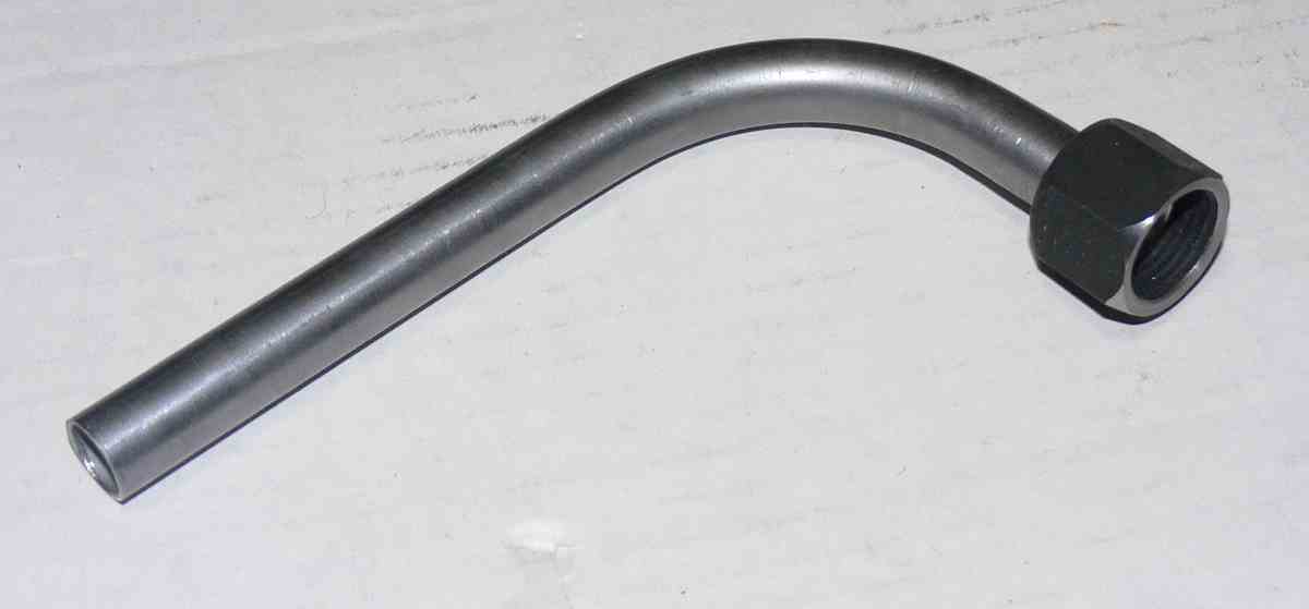
 When bending the Al or any tube, a quality bender gives MUCH better bend
 quality. The less expensive benders have a tendency to leave a small
 "crimp"
 in the tube or scratch the outside. A bit of grease or anti-seize on the
 tube and bend shoe helps prevent galling of the tube. I highly recommend
 the Swagelok benders, however they are expensive. If you can rent some
 it will be to your advantage or get someone who has a set to do the
 bending for you. The labor cost is offset by the superior job and that
 person should have at least the 3/8" and 1/2" benders. There is no
 Swagelok 3/4" bender so that can not be helped.

 Dale Davies
 Thanks Dale, Sorry for the late response, Work has been crazy. Anyway, I
 did look at the A-1210-1-12W but space is tight and if I want the
 fittings on the side of the tank I don't think I can make the bend in
 the 3/4" tub to make the turn for a straight fitting. And your right
 those tube benders are expensive, Maybe I can find someone that can loan
 me one when I get to the bending point.

 Thanks

 Mike C


Hey Mike,

Make sure that you use a mandrel bender to bend that tube.  There's no
way you can make a tight radius bend without wrinkling up the inside of
the bend if you don't use a mandrel bender.  I'm not suggesting that you
buy a mandrel bender, or even rent one.  They are way expensive.  Find a
pipe shop that has one and pay them to make the bends for you.

I understand that musical instrument makers fill their tubes with ice
before they bend them to avoid the wrinkled tubing syndrome.  I've never
tried it but I would imagine that it would take some experimentation to
get the technique down.

I've seen heavy duty coil springs sized to fit inside tubing to prevent
the bend distortion.  I haven't tried these either so again some
experimentation is in order.  Mandrel benders I've used and I know they
work.


Mark LaPierre

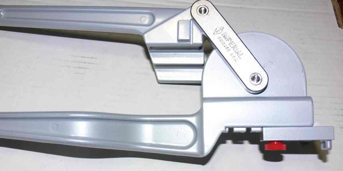
Here is the tube bender I use.

Paul Lamar


--
The Rotary Engine News Letter. Powered by Linux.
ACRE NL web site. http://www.rotaryeng.net
You Tube key word PaulLamar2
Copyright 1998-2012 All world wide rights reserved.