Hi Paul, what info do you need, to construct a cad model of a rotary
 engine mount for a tango XR? In broad terms the firewall dimensions
 are 42" wide x 26 3/8" at the widest points, the thrust line is
 approximately 11" below the top of the firewall. More accurate thrust
 line measurement to follow soon but11" is pretty close

 Also I have been chatting to Milo with the RV8 FWF for sale, there's
 obviously a lot of changes to make that fit, what we thought of doing
 was superimposing the rv8 mount over the tango XR mount to get an idea
 of what sticks out the cowling and would have to be moved, would you be
 able to help with this?

 Alex

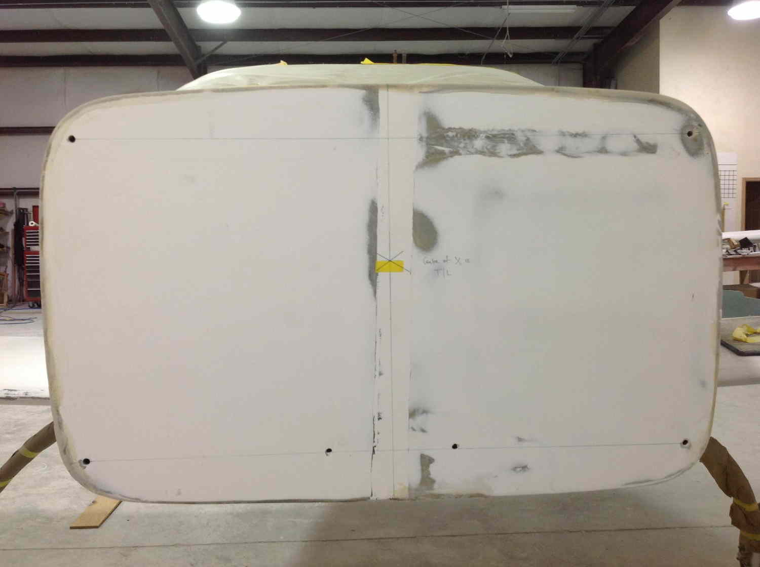
 The firewall dimensions. You can take a perpendicular picture of the
 firewall looking back at it and then tell me the max width. From that
 I can scale the dimensions that I need.

 Also i need the point on the firewall that represents the thrust line. A
 piece of tape will mark that point. This way I can do a cowl drawing to
 make sure everything fits. If you have a cowl we can use that. I need the
 lenght and the size of the spinner. If no cowl I suggest using an 18"
 spinner as the rotary engine is roughly round and that gives more room in
 the cowl.

 Paul Lamar

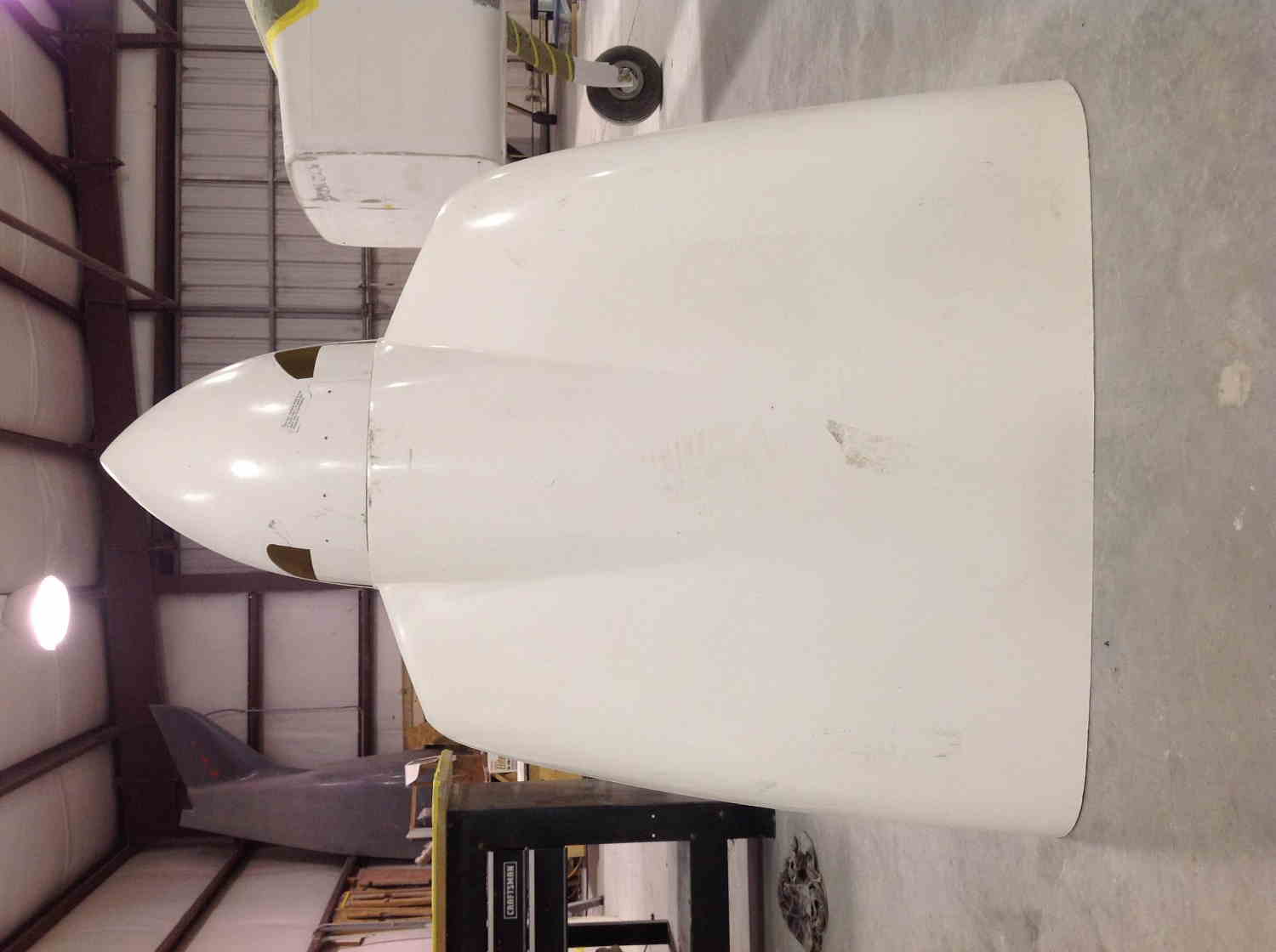
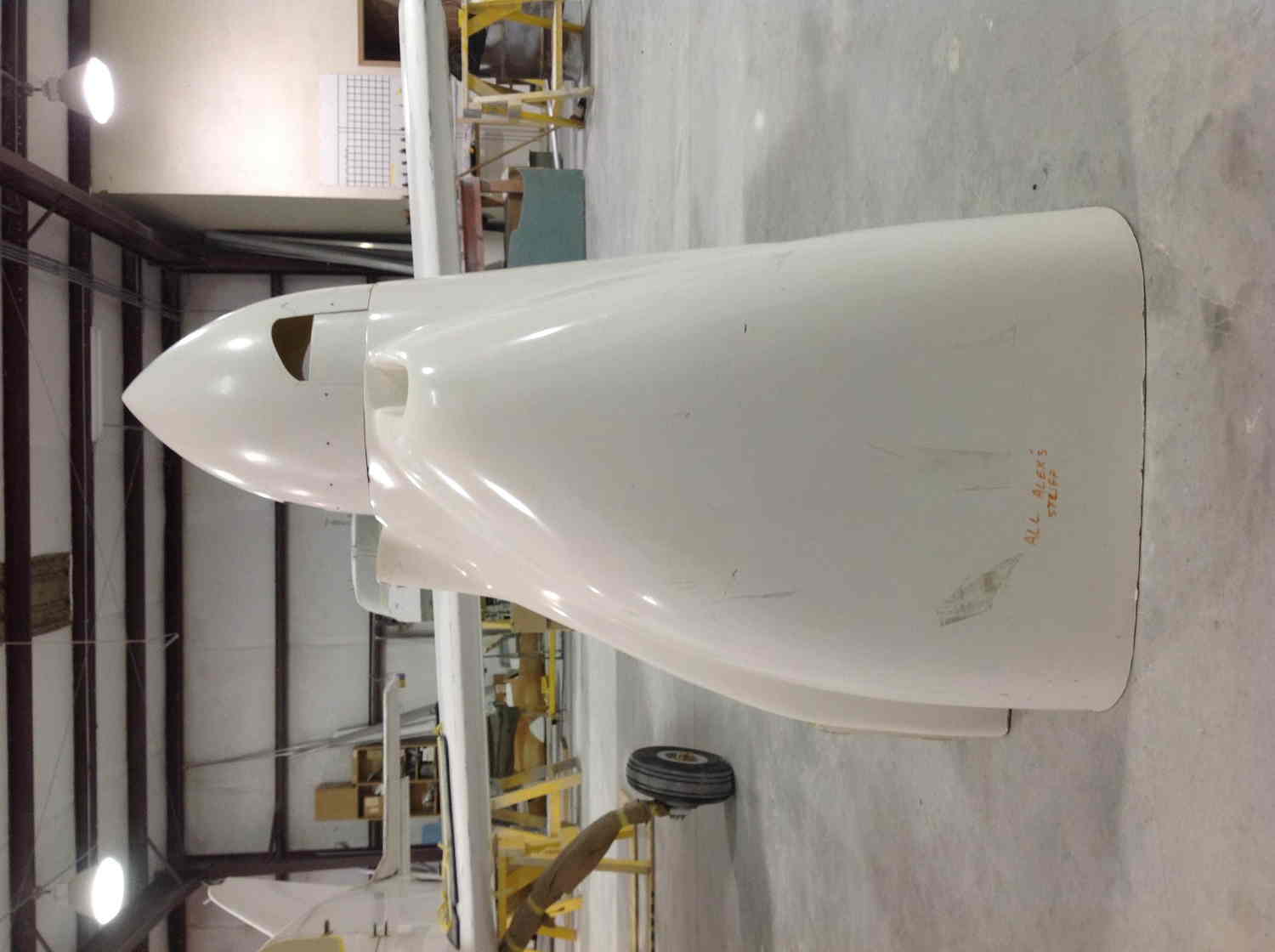
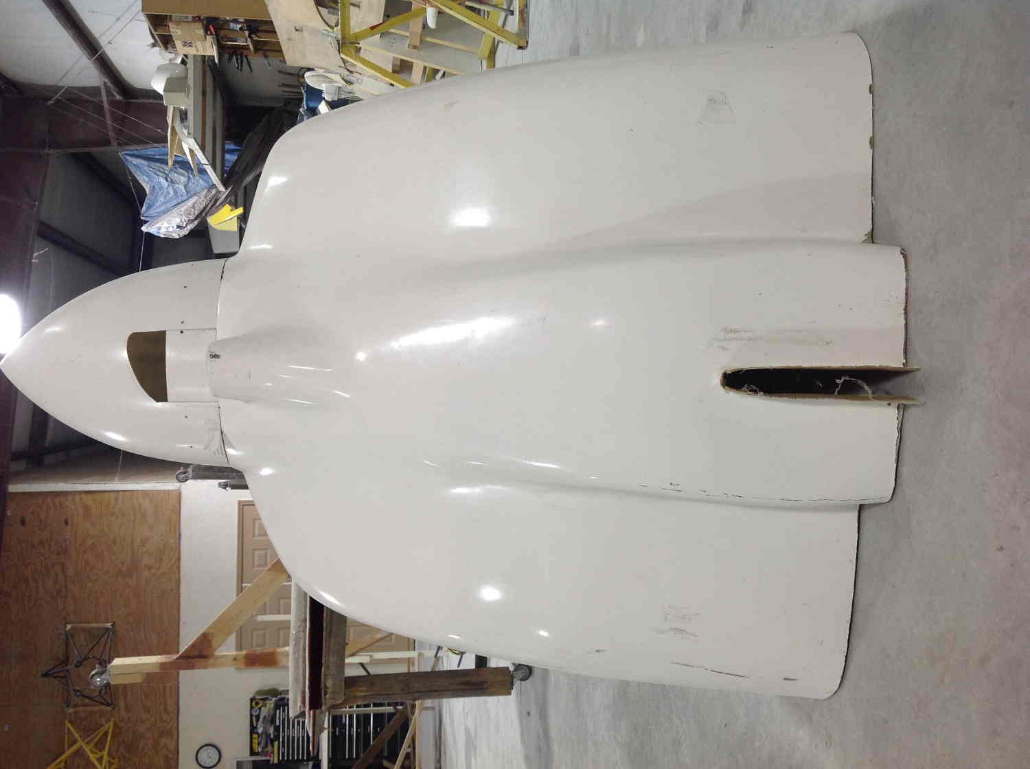
Hi Paul sorry for the delay I just got back to my project today, a
perpendicular picture of the firewall as well as cowling photos are
attached. The accurate dimensions are:

Firewall:

The thrustline is 10 7/8" down (from the top centre of the firewall) and
marked by an X, also marked as the line on the top edge of the tape.

Maximum firewall width is 42 7/16"
Maximum firewall height top to bottom along the vertical line is 26 5/16"

Firewall width running through thrust line marked by X on firewall is 42
3/8"

I still need to incorporate a 1.25 degree offset from the X point, (as is
required by the plans for the lycoming install) or can this be done with
computer modeling? I would prefer to offset the rear of the engine from the
X mark to achieve the required 1.25 degree offset, because the cowling i
have already has the offset built into it.

Cowling:

Length 36 3/4" (as measured along the top)
Spinner diameter 14"
Spinner 1 length 14.5" (same spinner as in the photo)
(Optional spinner 2) length 19"

Additional cowl info, lower cowl circular inlet is 2.5" inner diameter,
both forward air intakes are 2.5" wide and approximately 6.75" long

I'm planning on using Tracy's 2:85 reduction so thrust line offset would be
to the right as viewed from the cockpit and I was hoping to incorporate an
exhaust augmenter setup to help with cooling,

I forgot to mention, my pre drilled engine mount holes on the firewall are
both 37 15/16" apart from each other in width, and vertically 19 13/16"
apart, all measured from centre to centre. These holes are already
hardpointed to take the mount,


Alex Molteno


Good work Alex. I'll see what I can come up with.
Unless you want to put something under the fuse there will not be enough
room for a proper  exhaust augmenter. If the cooling diffusers are done
right there will be no need.

Paul Lamar
--
The Rotary Engine News Letter. Powered by Linux.
ACRE NL web site. http://www.rotaryeng.net
You Tube key word PaulLamar2
Copyright 1998-2012 All world wide rights reserved.