Hi Paul, what info do you need, to construct a cad model of a rotary
   engine mount for a tango XR? In broad terms the firewall dimensions
   are 42" wide x 26 3/8" at the widest points, the thrust line is
   approximately 11" below the top of the firewall. More accurate thrust
   line measurement to follow soon but11" is pretty close

   Also I have been chatting to Milo with the RV8 FWF for sale, there's
   obviously a lot of changes to make that fit, what we thought of doing
   was superimposing the rv8 mount over the tango XR mount to get an idea
   of what sticks out the cowling and would have to be moved, would you be
   able to help with this?

   Alex

   The firewall dimensions. You can take a perpendicular picture of the
   firewall looking back at it and then tell me the max width. From that
   I can scale the dimensions that I need.

   Also i need the point on the firewall that represents the thrust line. A
   piece of tape will mark that point. This way I can do a cowl drawing to
   make sure everything fits. If you have a cowl we can use that. I need the
   lenght and the size of the spinner. If no cowl I suggest using an 18"
   spinner as the rotary engine is roughly round and that gives more room in
   the cowl.

   Paul Lamar

  Hi Paul sorry for the delay I just got back to my project today, a
  perpendicular picture of the firewall as well as cowling photos are
  attached. The accurate dimensions are:

  Firewall:

  The thrustline is 10 7/8" down (from the top centre of the firewall) and
  marked by an X, also marked as the line on the top edge of the tape.

  Maximum firewall width is 42 7/16"
  Maximum firewall height top to bottom along the vertical line is 26 5/16"

  Firewall width running through thrust line marked by X on firewall is 42
  3/8"

  I still need to incorporate a 1.25 degree offset from the X point, (as is
  required by the plans for the lycoming install) or can this be done with
  computer modeling? I would prefer to offset the rear of the engine from
 the
  X mark to achieve the required 1.25 degree offset, because the cowling i
  have already has the offset built into it.

  Cowling:

  Length 36 3/4" (as measured along the top)
  Spinner diameter 14"
  Spinner 1 length 14.5" (same spinner as in the photo)
  (Optional spinner 2) length 19"

  Additional cowl info, lower cowl circular inlet is 2.5" inner diameter,
  both forward air intakes are 2.5" wide and approximately 6.75" long

  I'm planning on using Tracy's 2:85 reduction so thrust line offset would
 be
  to the right as viewed from the cockpit and I was hoping to incorporate an
  exhaust augmenter setup to help with cooling,

  I forgot to mention, my pre drilled engine mount holes on the firewall are
  both 37 15/16" apart from each other in width, and vertically 19 13/16"
  apart, all measured from centre to centre. These holes are already
  hardpointed to take the mount,


  Alex Molteno


  Good work Alex. I'll see what I can come up with.
  Unless you want to put something under the fuse there will not be enough
  room for a proper  exhaust augmenter. If the cooling diffusers are done
  right there will be no need.

  Paul Lamar

 Hi Paul
 I  hadn't firmed up my ideas entirely regarding the lower cowl setup. I
 thought i might need to hang a spintech muffler underneath the cowl if i
 need to quiet the beast downwhich would negate using an augmenter.

 i also wanted to go with a sub cowl design like Ed Vettermans (or better
 yet the one that was posted a couple of days ago on the newsletter) to
 clean up the cooling drag for any air exiting the bottom cowl. i know there
 is a bit of reverse flow going on there because where oil pools up on
 another completed tango next to mine, it doesn't streak and run backward in
 flight like usual, so I need to do something there anyway to clean it up.
 The current firewall design makes cowling air turn through an abrupt
 90degree bend on the bottom of the firewall, and after the bend no attempt
 is made at accelerating the cooling air back to free stream flow

 What I liked most about the augmenter idea was that with the pumping gains
 from the exhaust I could ditch the thermostat, cooling air flow through
 heat exchangers would be automatically regulated (more or less) by the
 amount of power I've set. Having such a wide range of hp my aircraft will
 be flying at, also helps keep the inlets from having to be oversize or
 undersize in order to be able to keep within limits.

 Alex

 It is not a good idea (I think) to use any commercail muffler. I am afraid
 you will need to weld something up. There is a possiblty that the guts will
 melt and plug the exhaust. Especially if you are using a 13B as opposed to
 an RX8 engine.

 Ejectors have to be rather long to work well.

 Paul Lamar

Paul, noted on any of the automotive off the shelf mufflers. It seems
tuning an ejector is a hassle too as a fixed size design only works for one
speed and air density, and its performance drops off on either side of that
optimum combination. I've read it can create more drag than it makes thrust
at higher speeds, if its tuned to provide adequate ground cooling which is
what i wanted it for.

I will try and optimize the cooling diffusers as much as possible, and
might look at shaping the subcowl as an "inverted turbulent flow wing" to
try and generate more of a low pressure area just aft of the firewall that
can suck out expended cooling air with some propwash over it,

Alex

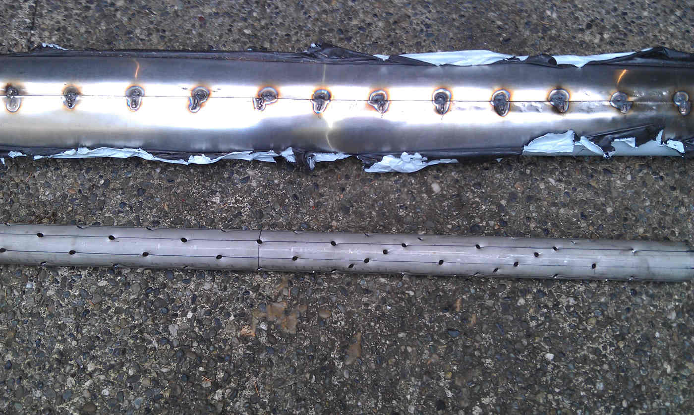
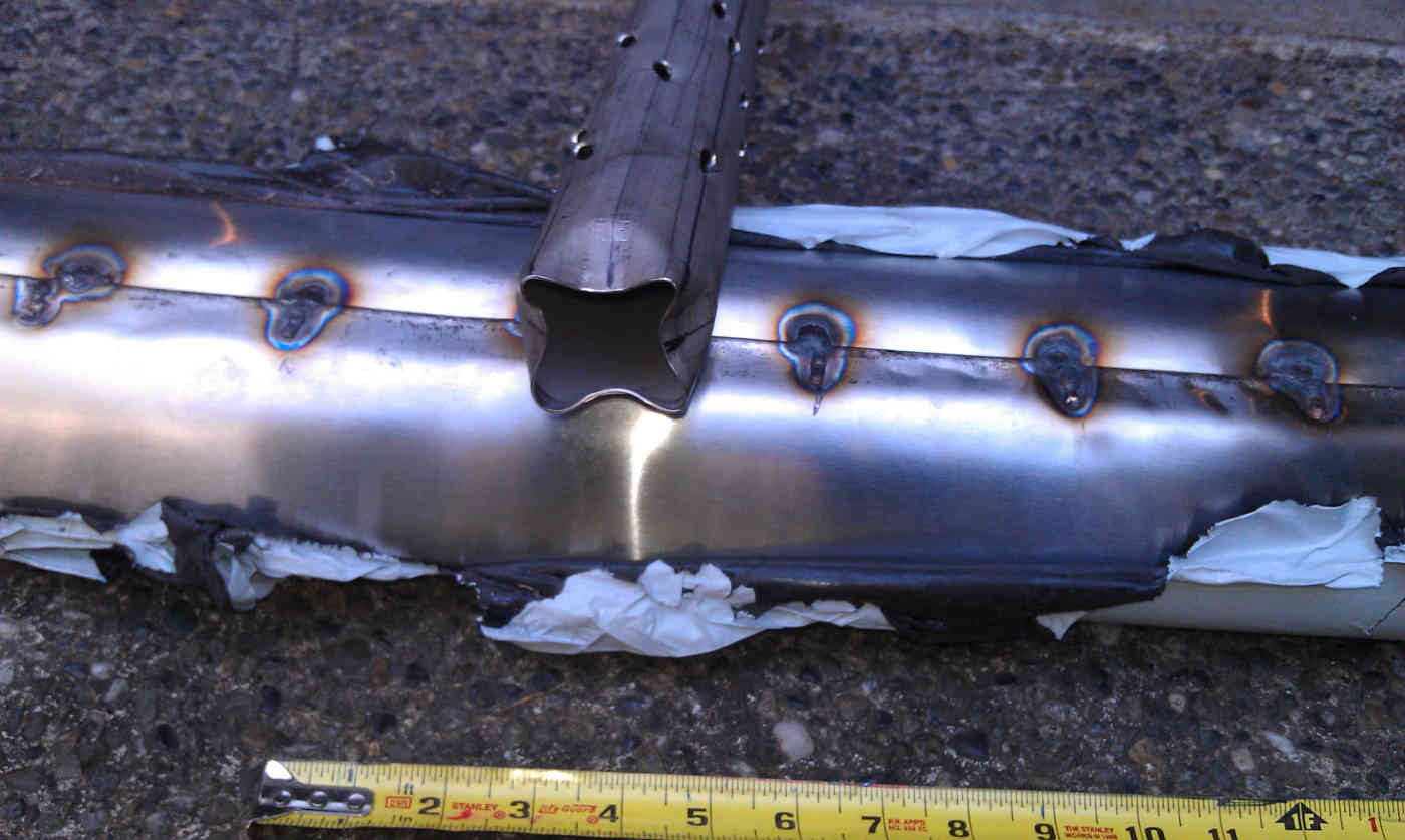
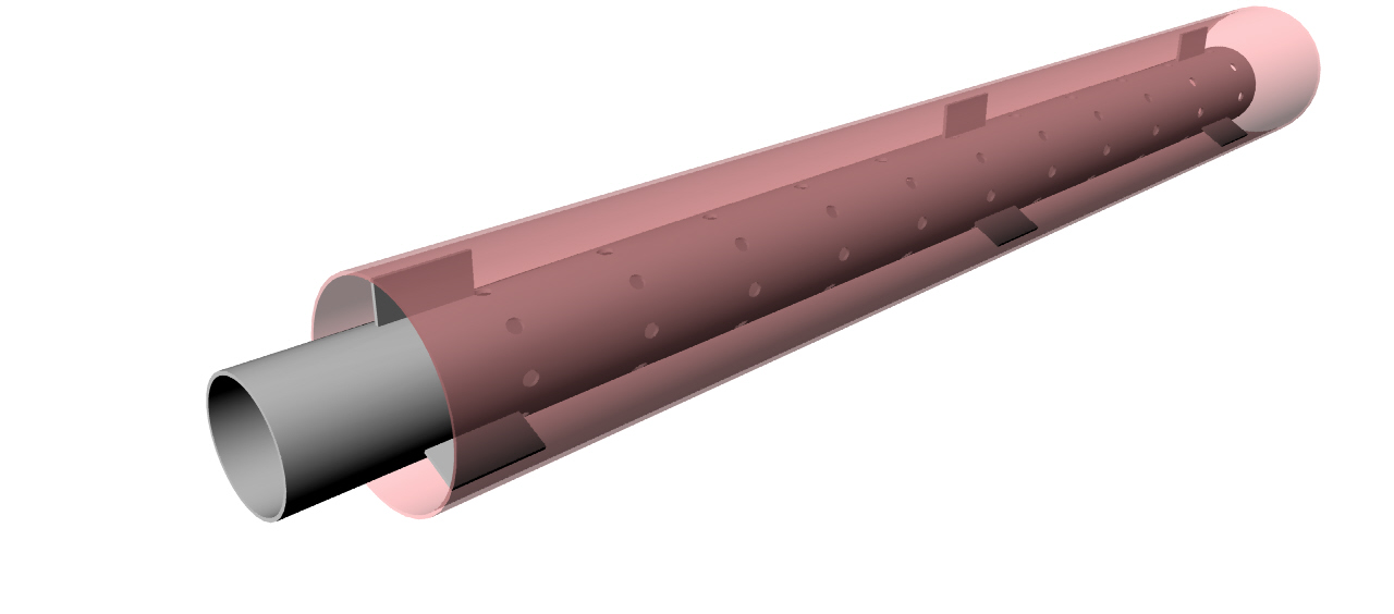
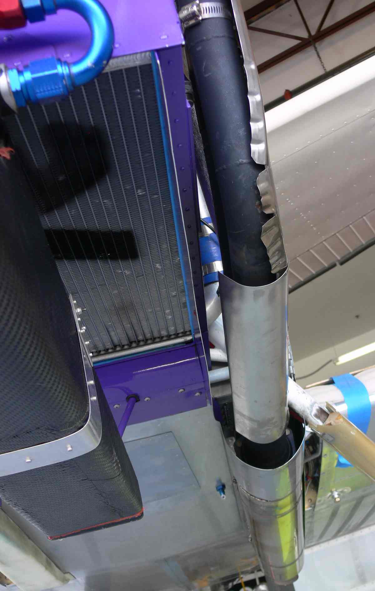
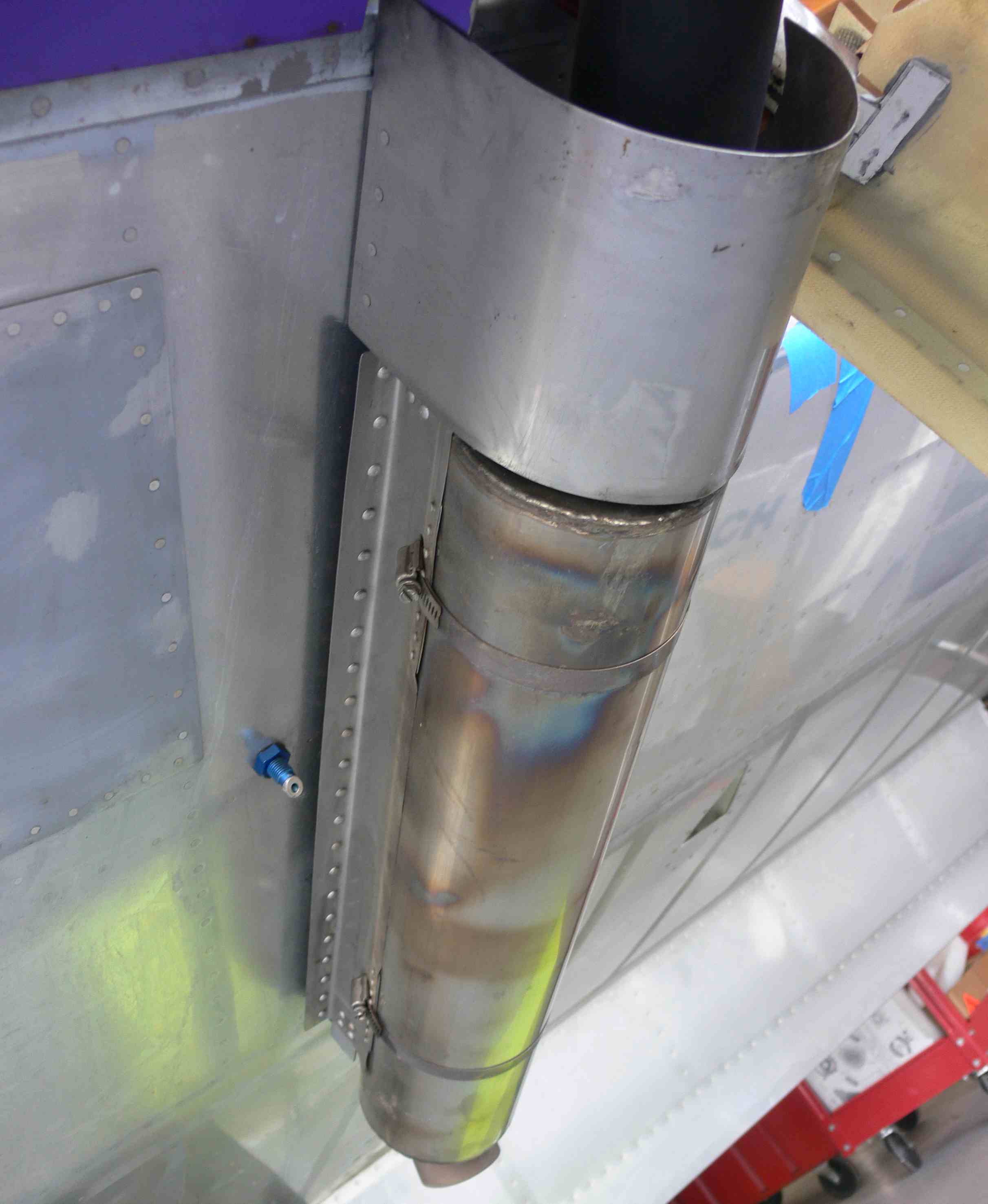
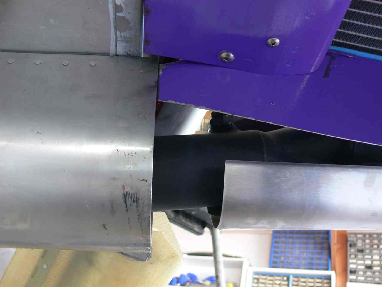
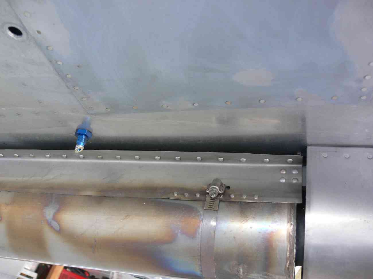
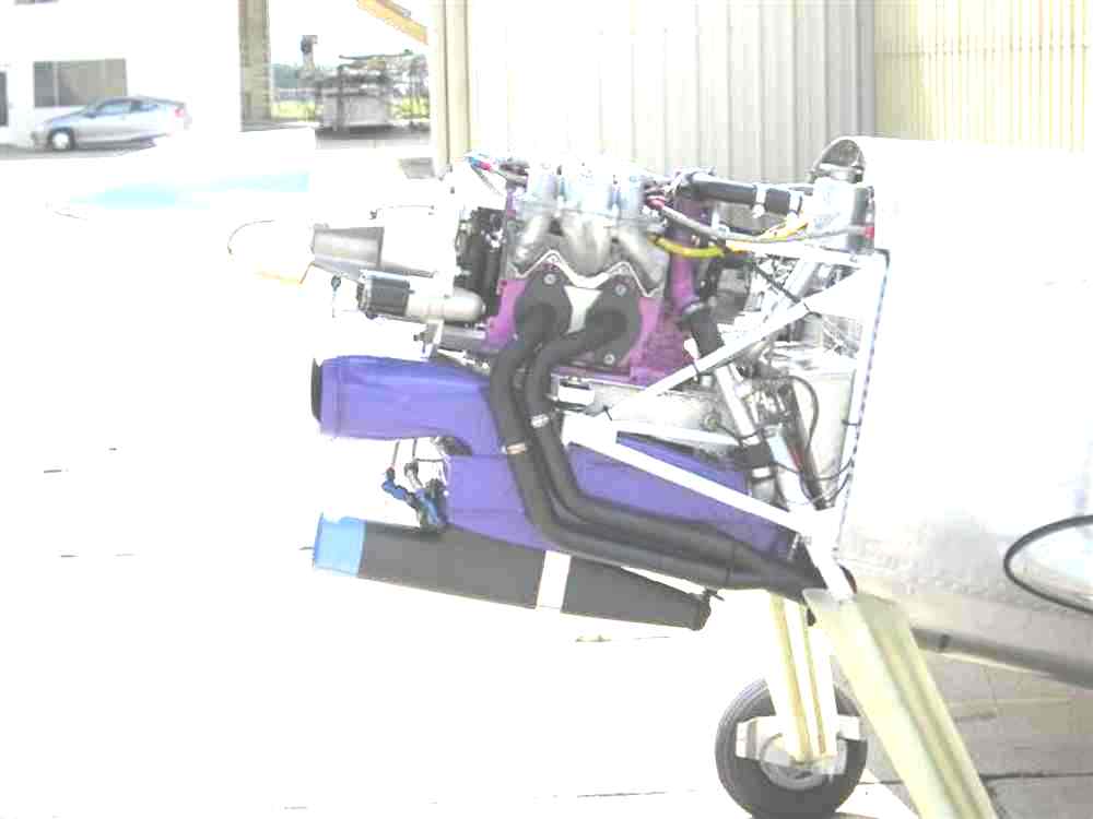
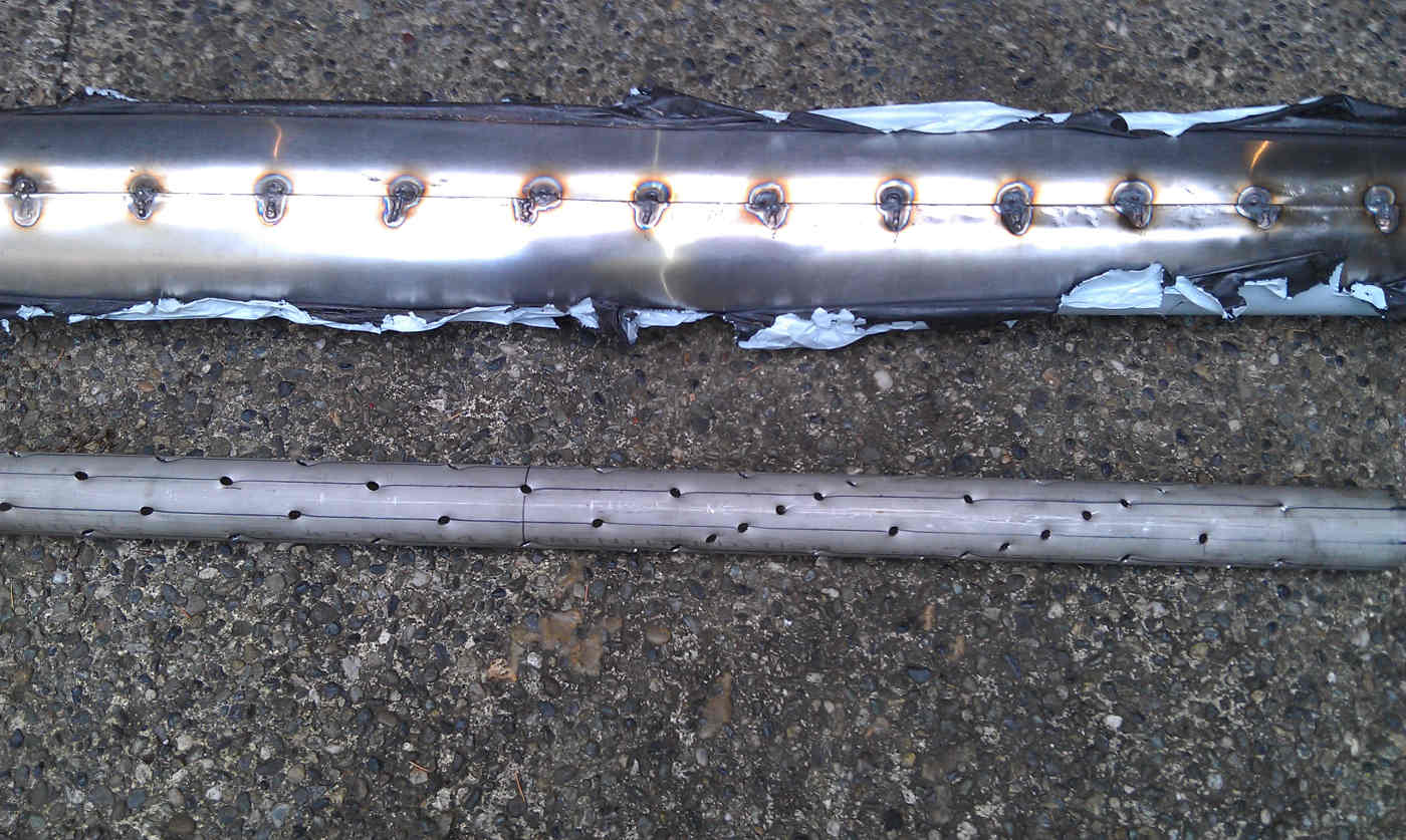
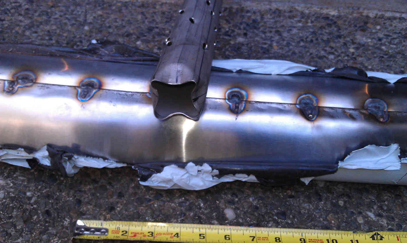
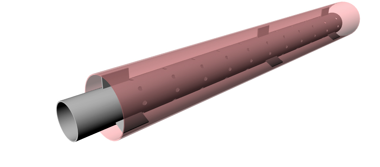
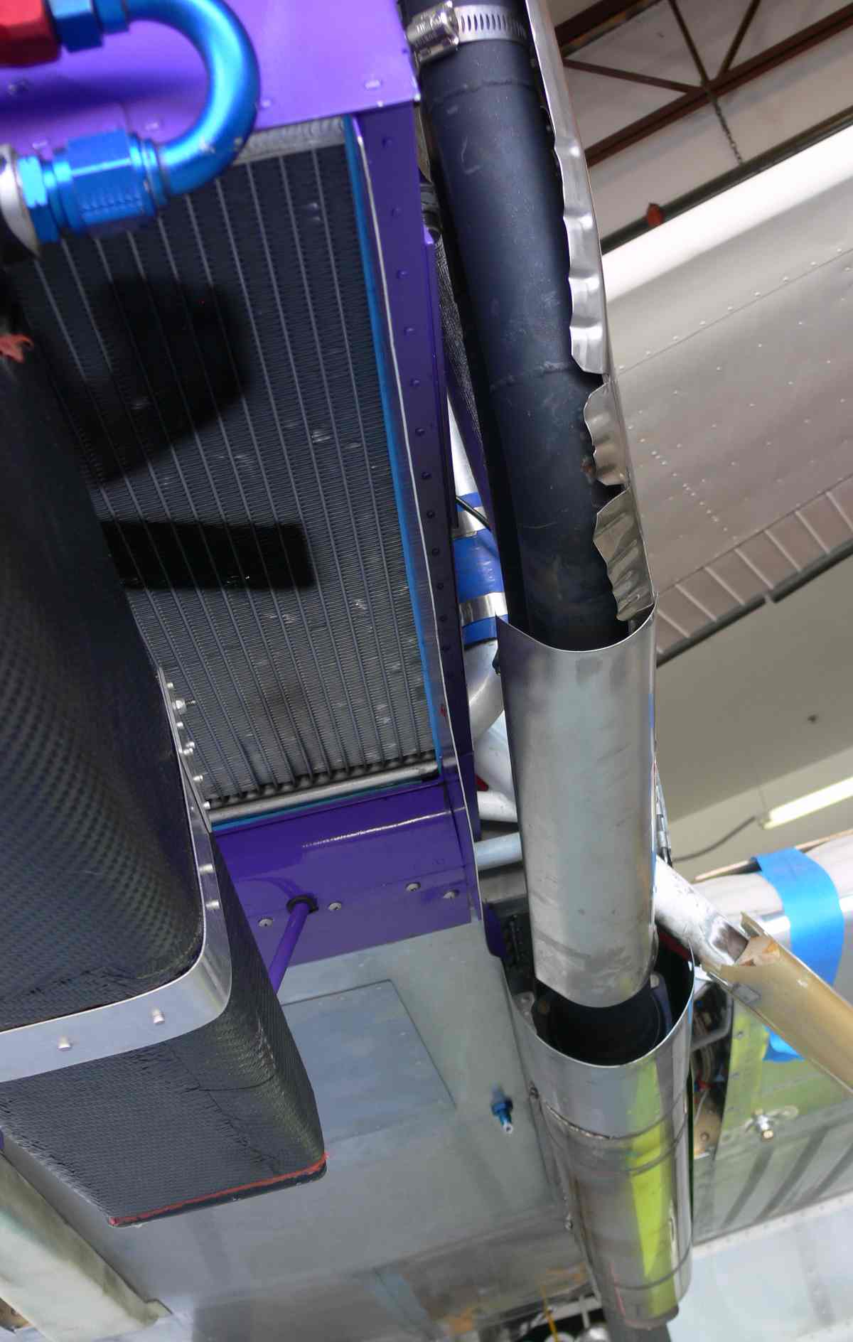
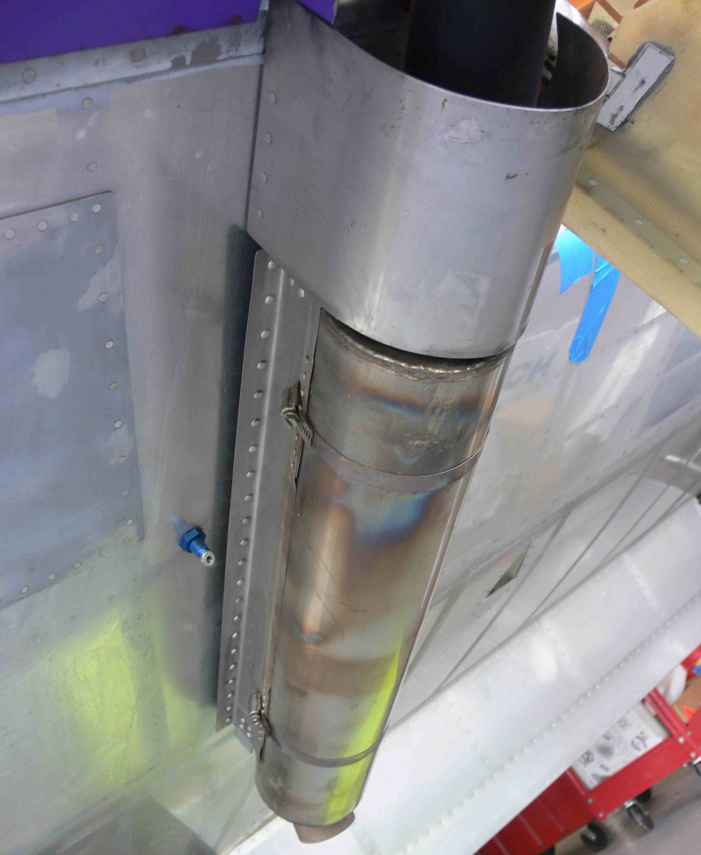
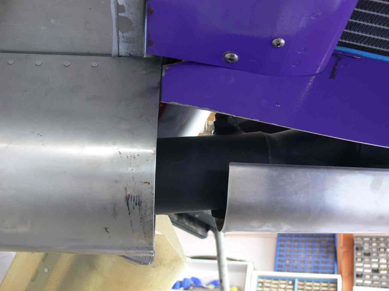
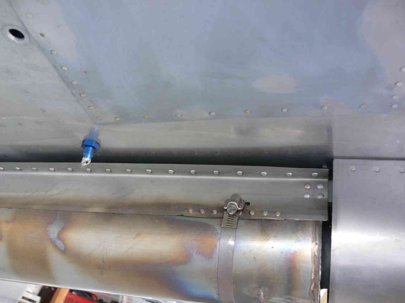
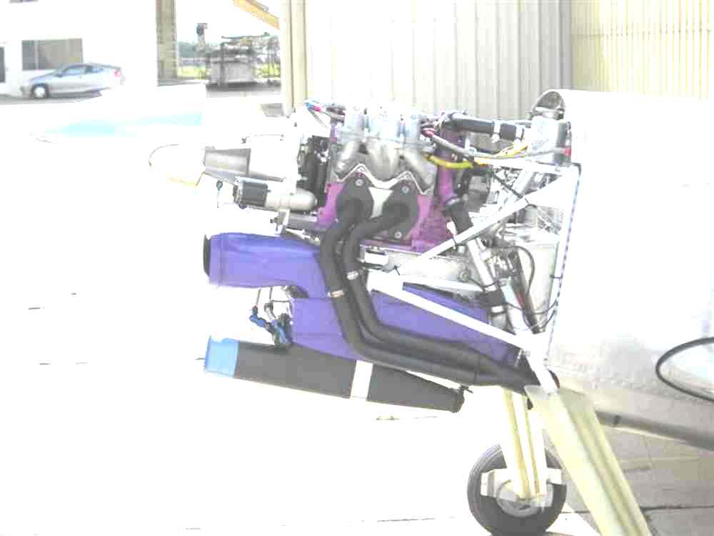
The trick is to use a long, small diameter coaxial muffler under the fuse like Brian
is building. That minimizes the frontal area increase and the aero drag yet providing
good silencing. The optimum hole sizes are yet to be determined.

Paul Lamar


--
The Rotary Engine News Letter. Powered by Linux.
ACRE NL web site. http://www.rotaryeng.net
You Tube key word PaulLamar2
Copyright 1998-2012 All world wide rights reserved.