Paul, what size bolts do you recommend for mounting to the firewall.
Is there a difference in bolt sizing between the 4 corner mounts and
landing gear mounts? Do you recommend different size firewall bolts for
the oil pan mount design versus the front plate mount design? My pre
drilled firewall holes are 3/8" is this good enough for a non p port
Renesis
Alex
The oil pan mount is problematic due to oil leaks and heat into the
rubber
mounts.
Usually 5/16th bolts hold the motor mount but you can go all the way
up to
3/8th with out adding much weight :)
I am thinking of mounting the hyd strut type nose gear to the oil pan
like the Questair Ventur. That way all nose gear loads are directly
reacted by the mass of the engine. What do you think?
Paul Lamar
Paul, I guess one could use the oil pan mount front mounting holes to react
the loads from the strut nosewheel into the engine. I imagine a forward
sweep of the strut like a C182 would be better, to make it more robust than
having a vertical strut. Then, can one use the aft 2 oil pan mounting holes
to secure the rear of the engine I wonder?
How would you brace the engine from the up loads generated from the nose
gear though, except through the rear oil pan mount with tubes in tension, I
mean, would a strut above the engine and attached to the firewall and in
compression, in a hard landing be enough to keep everything aligned to the
extent to prevent damage? Ive read the engine mount section of the website
several times, but i still don't feel clued up enough to make any real
assumptions I think :-)
The sweepback of the nose gear idea came from a nose gear incident on a
questair venture nose gear collapse in CA, its the third accident down
that page on the link
http://www.planesgalore.com/CaliforniaAirports/CA_Delano_Airport1.aspx
Alex
I copied the Questair Motor mount scheme almost exactly. In fact the
rubber bushing are exactly the same part number and brand.
The 2 rotor pulses twice per revolution. Average p-port torque is about
200 foot pounds. Peak pulse engine torque may be twice that. With a
2.85:1 psru the prop sees 5.56 pulses per prop revolution with an
average prop torque of about 600 foot pounds with a peak torque of up to
twice that depending on how well Tracy's torque isolator plate works.
At 2700 RPM that is 15,000 pulses per minute or 250 pulses per second.
Well above the 12 pulses per second natural resonant frequency of the
Barry rubber bushings. Therefore transmissibility is very low. Probably
less than .1. A good thing.
The best way to isolate the torsional vibration is spread the rubber
motor mounts far apart and use soft rubber bushings. This is precisely
what Jim Griswald did when he designed the Questair Venture front motor
mount which is what we copied for the rotary. In fact we used the same
type, size and brand of low cost rubber bushings as Jim used. These are
under ten dollars each while Lycoming rubber bushing can cost as much as
$100 each. Namely Barry Controls part number 2002.
Two wide spread rubber bushings is the main reason the Questair Venture
is one of the smoothest air planes flying. It was designed by Jim
Griswold of Piper Malibu fame and Ed McDonald. BTW IMHO a major
breakthrough in aircraft engine motor mounts.
We used to use a square beam similar to the Questair round beam but the
motor plate is an improvement on that.
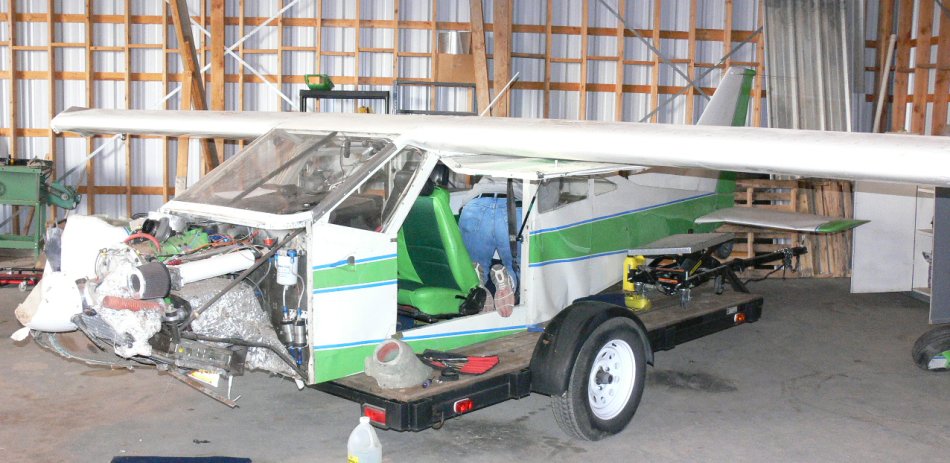
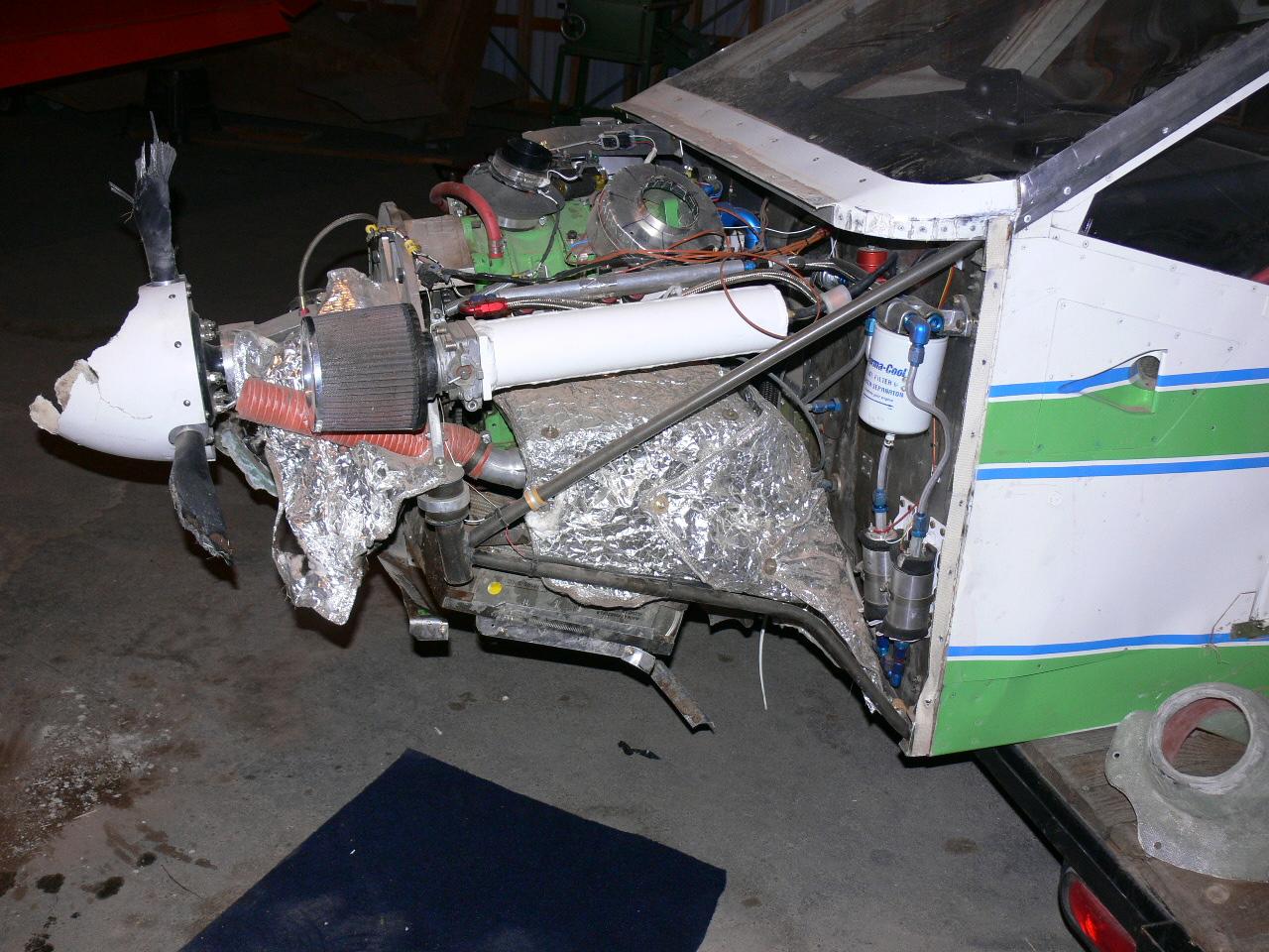
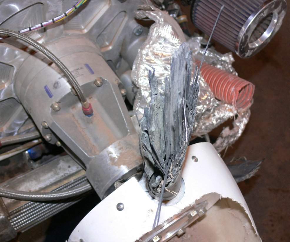
Our motor mount has been crash tested :)
I designed it to 6 G's.
One can damage any nose gear if one tries including the 182.
--------------------------------------------------------
BTW I forgot to mention with the oil pan plate sandwiched between the
oil pan and the engine that 600 ft pound prop torque must go through the
spacers and 10 mm bolts holding the gear box to the rear end housing of
the engine.
With Jeff's plate that 600 ft pound torque goes directly into the rubber
bushings, through the space frame and into the firewall and then
resisted by the wings.
There in lies the genius of Jim Griswald's design. It has all to due
with load paths. In his case the prop torque goes directly into the
engine crankcase since there is no 2.85:1 gear box and the piston
aircraft engine has enough cubic inches (IO-350) to develop high prop
torque directly.
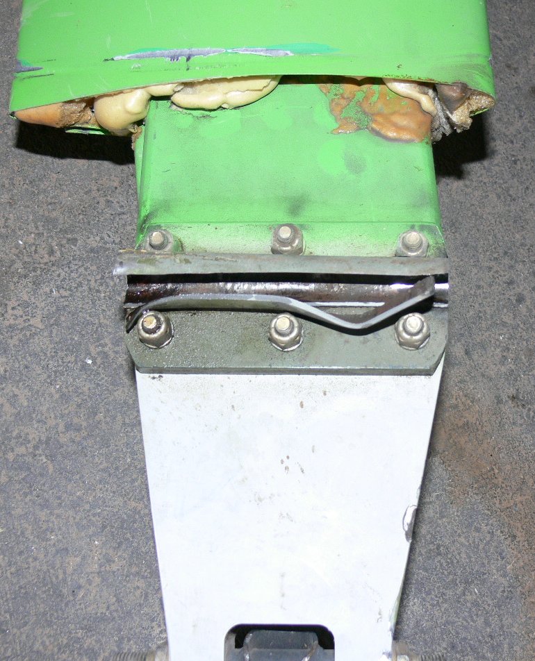
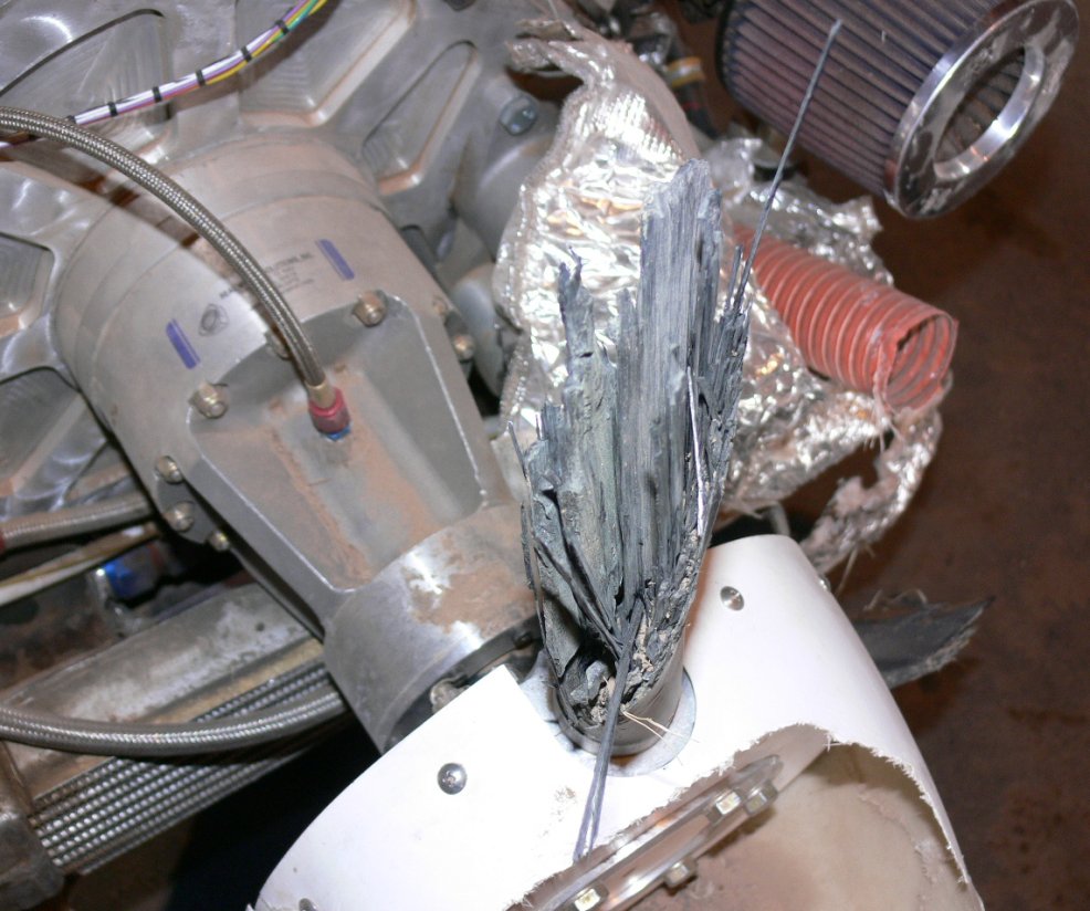
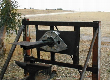
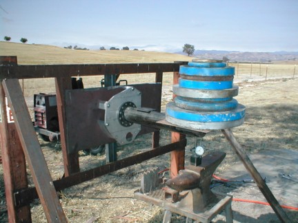
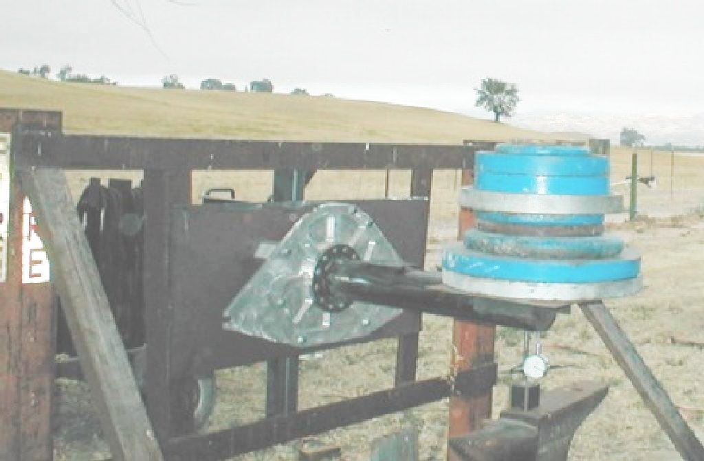
Here are some pictures of the crash and static deflection testing of
Jeff's plate mount :) We have since gone up to one inch tubes from 3/4
inch for the lower tubes subject to compression loads.
Paul Lamar
--
The Rotary Engine News Letter. Powered by Linux.
ACRE NL web site.
http://www.rotaryeng.net
You Tube key word PaulLamar2
Copyright 1998-2012 All world wide rights reserved.