#include <OneWire.h
// Wheeler Rotary ECU V0.2
//
//
//
// Mazda 13b Rotary Turbo Aircraft Engine
//
// Use 8bit variables where ever possible to speed processing.
// defines for setting and clearing register bits
#ifndef cbi
#define cbi(sfr, bit) (_SFR_BYTE(sfr) &= ~_BV(bit))
#endif
#ifndef sbi
#define sbi(sfr, bit) (_SFR_BYTE(sfr) |= _BV(bit))
#endif
// Cycle Time Variables
unsigned long MPST1; //time since PinCrank1- used to calc RPM
unsigned long MPST2; //time since PinCrank2 rotor 2
unsigned long MPST; //base var
unsigned long MSLastFallingEdge;
//These are unsigned long since they are microseconds, the numbers could get
really large.
byte Phase;
byte LastPhase;
unsigned long segTime;
//Engine Sensor variables
//Read from sensors- the characters after the = are pin numbers
float MapSensor = A1;
int CoolantTemp = A0;
float PWMpot = A6;
int InjManual = A7;
int PinCrank1= 11;
int PinCrank2 = 12;
int PinIndex; //Not used yet. If we need to sync, we will need this one.
// the one wire is a digital temp sensor
OneWire ds(2); // on pin 2
int PinIgnA = 3; // Fires coil for front rotor
int PinIgnB = 4; // Fires coil for rear rotor
int PinInj1 = 5; // for injector 1 for front rotor
int PinInj2 = 6; // for injector 2 for front rotor
int PinInj3 = 7; // for injector 1 for rear rotor
int PinInj4 = 8; // for injector 2 for rear rotor
//calculated
float celsius, fahrenheit;
float IntakeTempF;
int phase;
int IgnTimeA;
int IgnTimeB;
float Mixture;
float TempCor;
int RPM;
int Synchronized;
int InjPWM;
int InjPWM1;
int InjPWM2;
float kPa;
float mmHg;
int InAirTemp;
void setup(){
// set ADC prescale to 16, 21us per sample, without this the ADC will run
too slowly
sbi(ADCSRA,ADPS2) ;
cbi(ADCSRA,ADPS1) ;
cbi(ADCSRA,ADPS0) ;
Serial.begin(115200);
Serial.print("Aviation-Rotary ECU v0.4 by Kevin Alderman");
//pin mode definitions
pinMode(PinIndex,INPUT);
pinMode(PinCrank1,INPUT);
pinMode(PinCrank2,INPUT);
pinMode(InAirTemp,INPUT);
pinMode(MapSensor,INPUT);
pinMode(CoolantTemp,INPUT);
pinMode(PinIgnA,OUTPUT);
pinMode(PinIgnB,OUTPUT);
pinMode(PinInj1,OUTPUT);
pinMode(PinInj2,OUTPUT);
pinMode(PinInj3,OUTPUT);
pinMode(PinInj4,OUTPUT);
pinMode(Mixture,INPUT);
pinMode(InjManual,INPUT);
pinMode(PWMpot,INPUT);
}
void loop(void){
//The Engine needs to be turning over on the starter by this point.
//Time to Sync with the Engine with the Arduino...
//You might want to switch on the fuel pump here to fill the manifold
with fuel. I plan to add a
5 second fuel pump on time before the loop starts, so it will be a one time
deal. Other than that
the pump will run only with oil pressure.
//
Phase=1; //default Phase state
IntakeTempF=90; //default temp in case of sensor failure
kPa=100; //default pressure in case of sensor failure
mmHg=29.92; //default pressure in case of sensor failure
//Wait for the Index
// while(digitalRead(board.__PinCrank1==HIGH && digitalRead(board.PinIndex =
LOW))){
//Wait for the Crank- determine if signal is high- did tit pass sensor
while(digitalRead(PinCrank1==__HIGH)){}
MPST1=micros(); //Save the current time somewhere... will need this for
rpm and retard calcs
{}
{
// MSLastFallingEdge=micros();
// MPST1=(micros()-MPST1)/100; moved rpm calcs down to crank trigger
pickup
}
//We are now synchronized- was going to sync CAS and counter ring- //
decided to use separate sensors
// for each rotor. Time starts each time rotor1 fires.
}
void aquireAnalog(){
// MAP and Coolant sensors are analog- this is where we read them
MapSensor=analogRead(1); //reads pressure
CoolantTemp=analogRead(0);
PWMpot=analogRead(6); //will read signal from manual pot for manual
leaning
InjManual=analogRead(7); //manual push button for priming
Mixture=(60+(PWMpot*14)); //provides multiplier for injector pulse calc
kPa=((MapSensor-190)*.55); //convert map sensor ADC input to pressure for
inj pulse calc
mmHg=((MapSensor-190)*.1669); //converted map sensor to mmHg for display
in cockpit
//void aquireDigital(){
// InAirTemp probe is digital
// InAirTemp=digitalRead(OneWire)__;
// }
//////////////////////////////__////// Code for digital temp sensor
byte i;
byte present = 0;
byte type_s;
byte data[12];
byte addr[8];
// read the input on analog pin 0:
// float MAPSensor = analogRead(A1);
if ( !ds.search(addr));
// Serial.println("No more addresses.");
// Serial.println();
ds.reset_search();
delay(250);
return;
// Serial.print("ROM =");
for( i = 0; i < 8; i++) {
Serial.write(' ');
// Serial.print(addr[i], HEX);
}
if (OneWire::crc8(addr, 7) != addr[7]) {
// Serial.println("CRC is not valid!");
return;
}
// Serial.println();
// the first ROM byte indicates which chip
switch (addr[0]) {
case 0x10:
// Serial.println(" Chip = DS18S20"); // or old DS1820
type_s = 1;
break;
case 0x28:
// Serial.println(" Chip = DS18B20");
type_s = 0;
break;
case 0x22:
// Serial.println(" Chip = DS1822");
type_s = 0;
break;
default:
// Serial.println("Device is not a DS18x20 family device.");
return;
}
ds.reset();
ds.select(addr);
ds.write(0x44,1); // start conversion, with parasite power on at
the end
delay(750);// maybe 750ms is enough, maybe not
// we might do a ds.depower() here, but the reset will take care of it.
present = ds.reset();
ds.select(addr);
ds.write(0xBE); // Read Scratchpad
// Serial.print(" Data = ");
//Serial.print(present,HEX);
//Serial.print(" ");
for ( i = 0; i < 9; i++) { // we need 9 bytes
data[i] = ds.read();
// Serial.print(data[i], HEX);
// Serial.print(" ");
}
// Serial.print(" CRC=");
// Serial.print(OneWire::crc8(__data, 8), HEX);
// Serial.println();
// convert the data to actual temperature
unsigned int raw = (data[1] << 8) | data[0];
if (type_s) {
raw = raw << 3; // 9 bit resolution default
if (data[7] == 0x10) {
// count remain gives full 12 bit resolution
raw = (raw & 0xFFF0) + 12 - data[6];
}
} else {
unsigned char t_mask[4] = {0x7, 0x3, 0x1, 0x0};
byte cfg = (data[4] & 0x60) 5;
raw &= ~t_mask[cfg];
}
// default is 12 bit resolution, 750 ms conversion time
celsius = (float)raw / 16.0;
fahrenheit = celsius * 1.8 + 32.0;
// Serial.print(" Temperature = ");
// Serial.print(celsius);
// Serial.print(" Celsius, ");
// Serial.print(fahrenheit);
// Serial.println(" Fahrenheit");
// Serial.print ("Pressure kPa ");
Serial.println((MapSensor-190)__*.55);
Serial.print(" Pressure mmHG ");
Serial.println(mmHg);
//////////////////////////////__/end of digital temp probe code//////
segTime=micros(); //time rotor 1 fired recorded for rpm calcs
// closeInjector(); //if needed to force 0 pulse for injector- does not
appear to be needed
//Calculate Next Time of Ig Based on RPM.
// IgnTimeA=segTime+(sparkTime()*__MSPT
digitalRead(PinCrank1);
while (PinCrank1== HIGH)
{
digitalWrite(5,HIGH);
MPST1=micros();
}
digitalRead(PinCrank2);
while (PinCrank2==HIGH)
{
digitalWrite(6, HIGH);
MPST2=micros();
}
RPM=((MPST2-MPST1)*6000000);
Serial.println(RPM);
segTime=micros();
// Phase++;
if (digitalRead(PinCrank1==HIGH && digitalRead(PinIndex == LOW)))
{
phase=0;
}
else
{
phase=1;
}
// In the CAS when the top rotor 1 tit passes the pickup, the lower toothed
ring is between teeth.
//Calculate RPM... Microseconds per 1/12th of a revolution in our case-
stock CAS lower ring has 24
teeth-
// and rotates half engine speed. Hence, 12 teeth per rotation
MPST =(segTime - MSLastFallingEdge) 12;
MSLastFallingEdge = segTime;
Mixture = ((PWMpot*.10)+.4); //mixture pot reads voltage from pin, adjusted
manually. The constant
.4 is for fine tuning of system later.
TempCor = ((fahrenheit/4)*-1); // the calcs adjust mixture based on temp. By
default if no temp
input, temp would be 90 F
if (fahrenheit 200, TempCor= -40);
if (fahrenheit < 1, TempCor=0);
//Calculate Injector pulse width
InjPWM = (100+((kPa*.91)-TempCor))*(__Mixture/.001); // this is the calculated
pulse width based on
typ 550 injectors- 2 per rotor.
InjPWM1 = InjPWM; // sets the injector pulse width for the first injector
InjPWM2 = 0; // sets the injector pulse width for the second injector
// the PWM of 255 is full time on. If the PW is more than 200, calculate
//difference and start
using 2nd injector.
if (InjManual 900)
{
(InjPWM = 255);
}
if (InjPWM 200)
{
(InjPWM1=200) && (InjPWM2 = (InjPWM-InjPWM1)); //100% flow is 255. To
keep from running at
//100% duty, at 200 we start to split the flow between the other
injectors.
}
else (InjPWM1 = InjPWM); //If the PWM is 200 or less, we can use only the
one injector.
if (RPM < 100)
{
return;
}
//wait for the right time to turn on injector. Injectors turn on last
because if the engine is not
//running, we dont want the injectors to keep pumping fuel.
//while(micros()<=InjTime){}
// openInjector();
analogWrite(PinInj1,InjPWM1);
analogWrite(PinInj2,InjPWM2);
analogWrite(PinInj3,InjPWM1);
analogWrite(PinInj4,InjPWM2);
//////////////////////////////__//////////////////////////////__////////////
}
Kevin,
Not sure about your math, but did notice that you assign value to
MPST1 in two different parts of your program. I think that has
something to do with your not getting right RPM. I notice the
statement
"MPST1=micros()"
in
"void loop(void)"
and in the while loop
"while (PinCrank1== HIGH)
{
digitalWrite(5,HIGH);
MPST1=micros();
}"
regards,
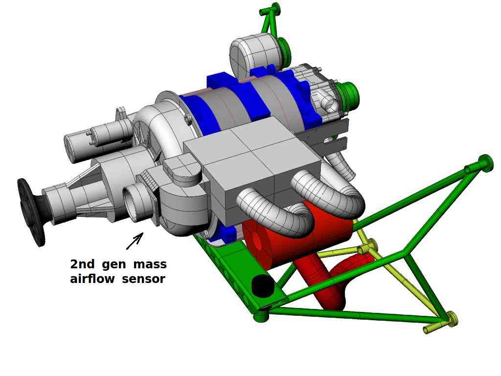
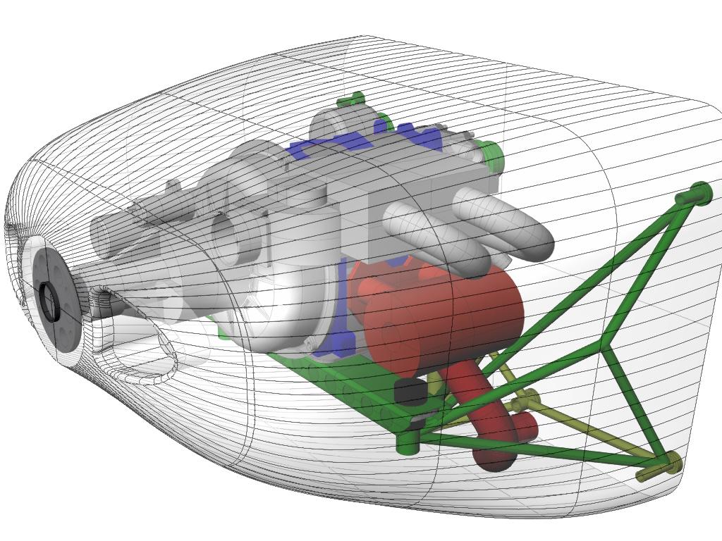
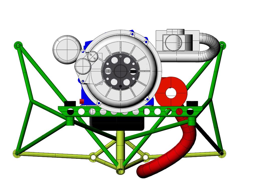
Henry NeeThanks Henry, I will see if that changes anything. Right now I am trying to build the
intake, which
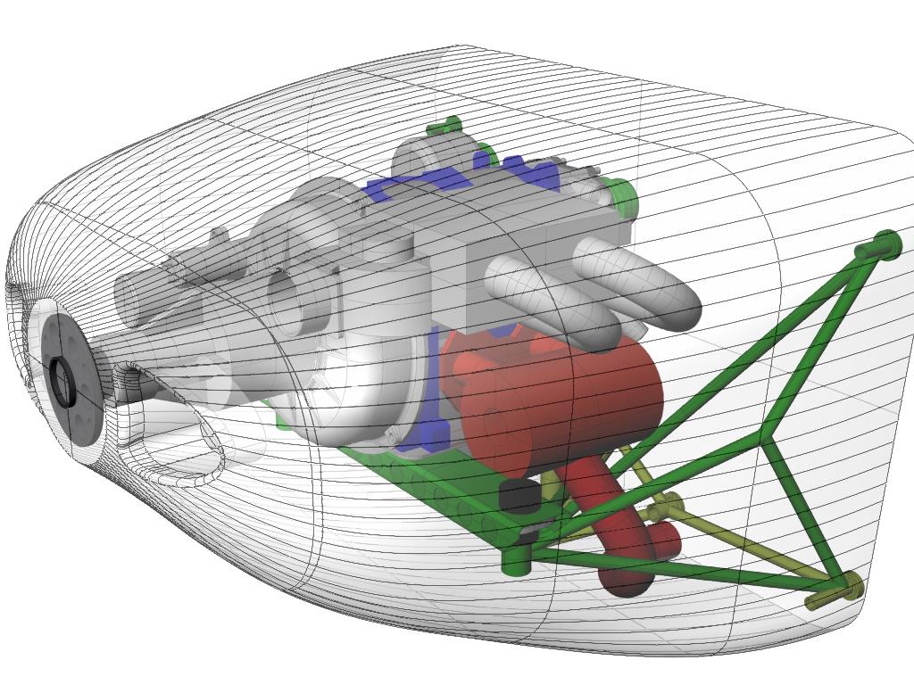
isnt that difficult. Keeping it under the cowling, a bit harder.
So goes progress!
KA
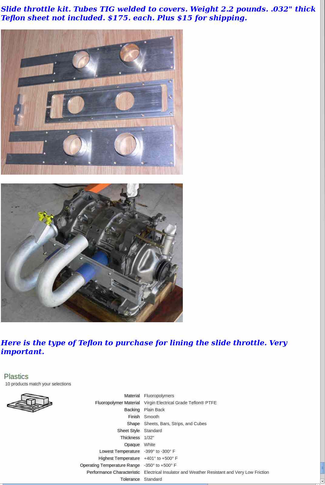
I have a cash sale on slide throttle kits.
$150
Paul Lamar
The Rotary Engine News Letter. Powered by Linux.
ACRE NL web site.
http://www.rotaryeng.net
You Tube key word PaulLamar2
Copyright 1998-2012 All world wide rights reserved.