Hi Guys
I'm about to construct the diffuser for the water exchanger.
Can some of you guys with operating setups critique the design please.
So it consists of a K&W diffuser followed by a wedge.
And a happy Christmas to you all.
Steve Izett
Perth Western Australia
Change the 5.75" dim to about 2 inches.
The idea is to keep a constant cross sectional area duct up to
the K&L wedge diffuser. That minimizes the tendency to get wall
separation in the duct due to a drop in pressure.
Also raise the core in the cowl as far as you can.
It would be less risky if the core was 19.5" instead of 17.5 long.
It might work at 500 cubic inches but 600 cubic inches would
be better. Check out pick up truck cores.
---------------------------------------------------------
Let me expand on this. It is very difficult and tedious at best to
design and build a K&W diffuser when you are dealing with offset
openings. Particularly if the openings are a different shape.
So keep it simple and use a constant area duct in conjunction with
a K&L wedge diffuser.
Paul Lamar
Thanks Paul
Will rethink design.
Steve
I did not put that in the book. However I did put a 3d in the book that
gives the impression that a K&W diffuser can be used with
a K&L diffuser. Sorry about that. On further thought it is a bad
idea for reasons outlined above.
I was thinking about it some more today and I think I have it figured
out how to draw and build a S shaped constant area duct using
a Rhino built in function. Straight walls are not the best. That
S shaped duct will give a smother transition from a typical AC cheek
scoop to a side mounted rad.
Here it is. Rhino is an amazing program to be able to do this in
15 minutes. It will take you a lot longer to build it :)
This is your Christmas present :)
Paul Lamar
Merry Christmas.
Thanks for putting your head around this. My first thought was exactly
that. Rotate the duct to match the K&L. I thought I could make it out
of
1/2 foam pieces then smooth, seal layup etc. See diagram attached.
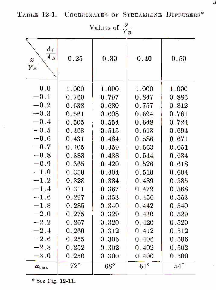
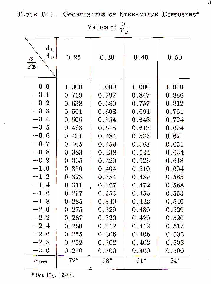
I was basing the design in K&W, specifically: In K&W Ch12 p.277 we read
"The use of streamline diffusers is not limited to the symmetrical case.
Any
other streamline of the free flow about the conducted cooler block may be
used as a wall. Tests where the straight centre line was taken as the
second diffuser wall (this has the highest pressure gradient) gave
results
only slightly inferior to the sometrical diffuser." And on the next page
p.278. "It was found that the losses were again about the same as those
for the symmetrical streamline diffuser."
Steve
That is great that you have the Kuchemann and Weber book
"Aerodynamics of Propulsion". That is a collector's item.
Here is the illustration you refer to. Did you find it in Oz?
That is a great idea for making the form. I'll have to remember that.
Pay attention folks. This is important. Just be sure the inlet
area is the same as the outlet area as in the 3D's.
I admire you Steve for your stoicism in the face of great adversity :)
Your a saint. Keep that chin up as you always do.
Paul Lamar Merry Christmas
Thanks Paul
No I don't have the book, just a copy of chap 12 that someone posted ages
ago. Can you explain why we wouldn't diffuse, even a little to reduce the
velocity of the airflow prior to entering the K&L diffuser? Hope you have
a great Christmas.
Steve
I theory that should work. It should reduce the velocity of the air and
the skin friction drag in the duct between the scoop and the K&L diffuser.
The problem is designing a complex shape 3D K&W duct that will work.
The area must gradually increase according to K&W theory.
It would be interesting to try. One would want to instrument it
with a zillion pressure taps and record the wall data pressure while
testing it in a wind tunnel.
One would first use the K&W coordinates to make a symmetrical 3D dwg.
Then plot the area along the straight center line. Then construct a
non straight center line between the two non similar and non axial
openings. Then assemble area disks at right angles to the new center
line every few inches. Fill in the gaps and hopefully your done.
Now the problem is; air has a range of characteristics like inertia,
adhesion and viscosity. Think of watery molasses.
Can one really expect this to work under those circumstances ?
My gut reaction is no :)
If air tends to stack up in one part of a constant area duct the pressure
increases in that area forcing the air to conform to the duct shape. It
is self stabilizing intuitively I would think.
Paul Lamar
Steve
You are well aware your father is a simple fellow. I am trying to get my
small mind around what we have been theorizing over the last few days. Is
Paul now saying it might not be a bad idea to increase the volume and
therefore reduce the velocity of the air as it moves from the inlet to the
wedge. This was our original intention. If that is so is the ratio of 1:3
not about the right order of things as we have been advised by others and
should not the volume increase slowly over about the first 2/3 of the length
and then expand "exponentially" to the wedge inlet giving as best we can a
trumpet shape.
The shape Paul shows at the bottom of his diffuser at the wedge entrance is
the very opposite in shape to what we understand gives the best pressure
distribution at this point.ie the opposite to a trumpet profile. What am I
missing?
I am well aware of the variable characteristics of air flow which Paul
rightly states. Our air flow will not be laminar (me thinks) but will be
turbulent and cannot with certainty be understood in our winding expanding
diffuser. Note that "uniform flow only occurs when the magnitude and
direction of the velocity does not change from point to point in a fluid".
This is not what we have here. Also because of the boundary layer effect the
velocity distribution will not be even but will be tending to a parabolic
profile with the velocity in the centre of the air flow some what greater
than at the boundaries. However the pressure distribution for turbulent flow
is more even than for Laminar flow which should help. What makes a truly
theoretical analysis of the pressure profile in our case nigh on impossible
(apart from its contortional shape) is because of changes in the aeroplane
speed through the air and the changes in air density due to altitude
changes.
The best we can ever hope for is to approximate the ideal. That is
what I think we are trying to do in using empirical results gained from
certain sets of test conditions that in most cases are vastly different to
ours. As you rightly have said to me on a number of occasions it is far more
useful for us to copy if at all possible duct configurations used by others
that have actually worked. The difficulty is finding some one that has a
similar arrangement to ours and has built a diffuser that works. Maybe that
some one does not exist and we will just have to do what we think best.
Help I am drowning
Dad
ps It just occurred to me is the trumpet shaped diffuser an attempt to
maintain laminar flow in a duct. If we can never, for other reasons, achieve
laminar flow then does it really matter if we for go the trumpet.
Bob Izett
The Rotary Engine News Letter. Powered by Linux.
ACRE NL web site.
http://www.rotaryeng.net
You Tube key word PaulLamar2
Copyright 1998-2012 All world wide rights reserved.