Paul,
Is it feasible to use a solid case, instead of a split case using inside
snap rings to separate the rotating elements?
milo
In theory yes because the rear flange is bolted on.
But given what I little I know about overhauling
piston engines bearing shells halves are a bit over size so when you torque
the case bolts... the shells compressed slightly and are held securely in place.
All you piston engine guys out there chime in on this.
The other problem is the oil slinger near the front of the shaft
but there is a work around for that.
Paul Lamar
------------------------------__----------------
Forgive me for my lack of attention to this, but is someone planning on
fabricating a kit or an entire psru that will provide oil pressure to a CS
hub? If so, are there any plans on a governor, and what are they? I would
be interested in a CS psru, seems Mistral is gone to never never land......I
don't think anyone makes one, that outfit in Canada with the spur gear drive
did for some time, but seems to have faded.....
Marc W
Yes. That is what Milo is up to :)
You will have to drive the gov with a cog belt off the nose
of the e-shaft.
Paul Lamar
/"You will have to drive the gov with a cog belt off the nose"/
/
/
Is there any reason that we cant drive the gov off of a plate where the old
oil injection unit went? There is an oil
port behind it that lubed the shaft, it turns, I think, at half engine speed
which is good for the gov, no belt to deal
with, etc. We would need a plate of aluminum about 1/2 inch thick with a
slotted to spline adapter kind of like a
continental starter drive. The mounting block would provide porting for
supply and discharge oil. Unless I am missing
something, I would think this would work.
Comments?
Kevin Alderman
I would think they have to be driven at prop RPM.
It is a fly ball gov.
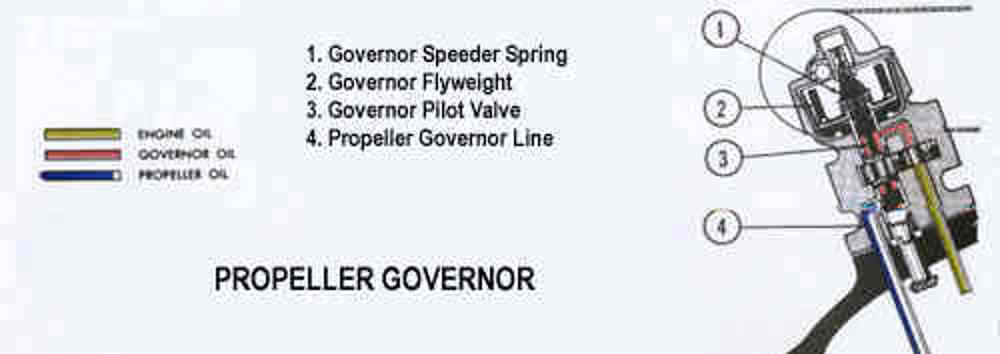
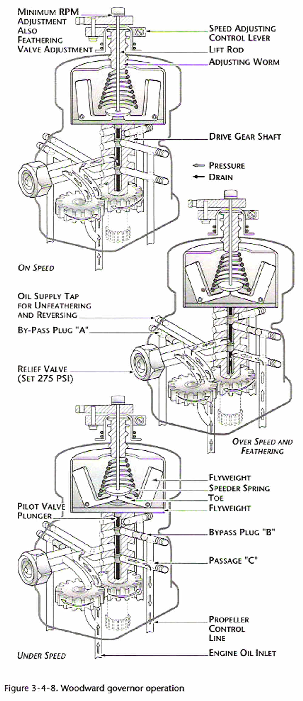
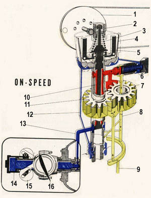
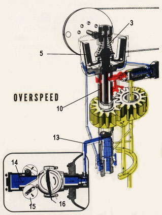
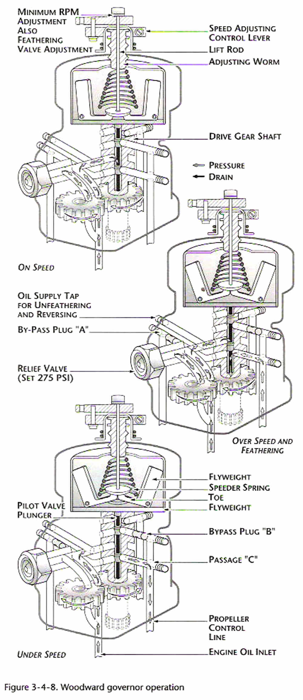
"Governor Operation (Constant speed with counterweight ) the Governor
supplies and controls the flow of oil to and from the propeller. The engine
driven governor receives oil from the engine lubricating system and boost
its pressure to that required to operate the pitch-changing mechanism. It
consists essentially of :
1. A gear pump to increase the pressure of the engine oil to the pressure
required for propeller operation.
2. A relief valve system which regulates the operating pressure in the
governor.
3. A pilot valve actuated by flyweights which control the flow of oil
through the governor
4. The speeder spring provides a mean by which the initial load on the pilot
valve can be changed through the rack and pulley arrangement which
controlled by pilot.
The governor maintains the required balance between all three control forces
by metering to, or drain from, the inboard side of the propeller piston to
maintain the propeller blade angle for constant speed operation. The
governor operates by means of flyweights which control the position of a
pilot valve. When the propeller r.p.m. is below that for which the
governor is set through the speeder spring by pilot , the governor flyweight
move inward due to less centrifugal force act on flyweight than compression
of speeder spring. If the propeller r.p.m. is higher than setting , the
flyweight will move outward due to flyweight has more centrifugal force than
compression of speeder spring . During the flyweight moving inward or
outward , the pilot valve will move and directs engine oil pressure to the
propeller cylinder through the engine propeller shaft."
Paul Lamar
The Rotary Engine News Letter. Powered by Linux.
ACRE NL web site.
http://www.rotaryeng.net
You Tube key word PaulLamar2
Copyright 1998-2013 All world wide rights reserved.