I had to go to the SF valley to check out a laser jet tube cutter
and MM welder and stopped off at a Pick a Part junkyard.
I found this GM LS1 mass airflow sensor for $45.
Retails for $399.95.
Took me five minutes to get it out of the wrecked Isusu truck.
All it took was 2 screw drivers a phillips and a straight :)
"Mass air induction systems measure airflow with an electronic
"hot-wire"
type mass airflow sensor. The sensing element in the air intake
provides an
output voltage reading that is directly proportional to the amount
of air
that is entering the engine. This airflow measurement reduces the
calculations required to control fuel and ignition spark advance.
Mass airflow sensors can react quickly and accurately to sudden
changes in airflow."
Usually it is 0 to 5 volts. I will use this with the Arduino program
and a slide throttle on the RV4.
They are easy to locate and mount as you put them upstream from
the slide throttle in 2.75 inch ID hose.
Paul Lamar
Hi Paul, The early types had a circuit that at switch off the wire
was heated to burn off any gunge sticking to the wire and cleaned
up the wire for next time engine was started. Hard to see the $400
value in those things.John Burey.
You can buy new ones made from plastic here for $100.
http://secure.ultracart.com/catalog/PSI/ACCESSORIES/MAF-
Sensors/ACC-1004.html
Connectors called pig tails here:
http://secure.ultracart.com/catalog/PSI/PIGTAIL-EXTENSIONS/LS-
Vortec-Pigtails/PIG-1019.html
While searching for a schematic for the LS1 MAF I ran across this
explanation
of the advantages of putting the injectors at the upstream end of the
p-port runner tubes.
http://www.hotrod.com/techarticles/engine/hrdp_9812_10_common_efi_mistakes/viewall.html
"Carbureted and throttle-body fuel systems are considered wet flow.
Port EFI
designs (an individual injector for each cylinder) are referred to
as dry flow. In a wet-flow system, a mixture of air and fuel
coarses through the intake-manifold runners; in port systems, the
fuel is administered at the end of the intake-manifold runner just
prior to entry into the cylinder head. The laws of physics dictate
that for every 10 degrees Fahrenheit of change in the temperature
of the charge, there will be a corresponding effect of 1 percent to
the specific output of the engine-raising the charge air
temperature will decrease power; cooling it will have the oppositeeffect. Wet-flow manifolds enjoy the advantage of
cooler charge airtemperatures created by the vaporization of the fuel. When changingfrom a liquid to a gaseous state,
this transformation will consume
some of the heat from the intake tract. Dry-flow manifolds do not
benefit from the latent heat of vaporization."
"The results of this phenomenon cause fuel-injected engines to be
affected
more by higher ambient temperatures and under hood heat."
"The best-running EFI cars breathe cold air from a ram-air kit."
-----------------------------------------------
Kevin's Arduino EFI code (attached) does not have a mass air flow
sensor input.
It works like Tracy's code on intake manifold pressure and air
temperature
correction I think. I suspect a mass air flow sensor would simplify
the code some what and most important the look up table.
In any event the 5 wire version of this mass air flow sensor has
a temp sensor for $2 more. A real bargain.
Paul Lamar
What about redundancy with a MAF sensor? Can you run two of them in
a row?
Everett Rankin
I don't see why not.
BTW I think one might be able to do away with the math in the EFI
program speeding it up greatly. Mass airflow changes with temperature
so no need to calculate the mass flow from intake man pressure
and intake air temp.
Paul Lamar
You could Everett, but two things. Each one does restrict airflow a bit. Two
would just be more. Another thing, that honeycomb is for two things. First is
to prevent large objects coming through and damaging the hot wire. The second
is "straightening vanes" to get the air from being turbulent.
Paul,
Previous discussion was that the MAF output was not linear and would cause an
issue to deal with to get the injection pulsewidth corrected?
Dale Davies
It is non linear and that concerned me when using them with a very simple
555 injection system. Now the price of powerful Arduino computers came
down to $20 bucks on Ebay. The non linearity of mass air flow sensors
can easily be handled in a look up table.
Based on my limited knowledge of Arduino programming it does not appear
Kevin is using a look up table. It appears to me he calculates the injector
pulse width based on MAP and intake air temp. This takes time as the Arduino
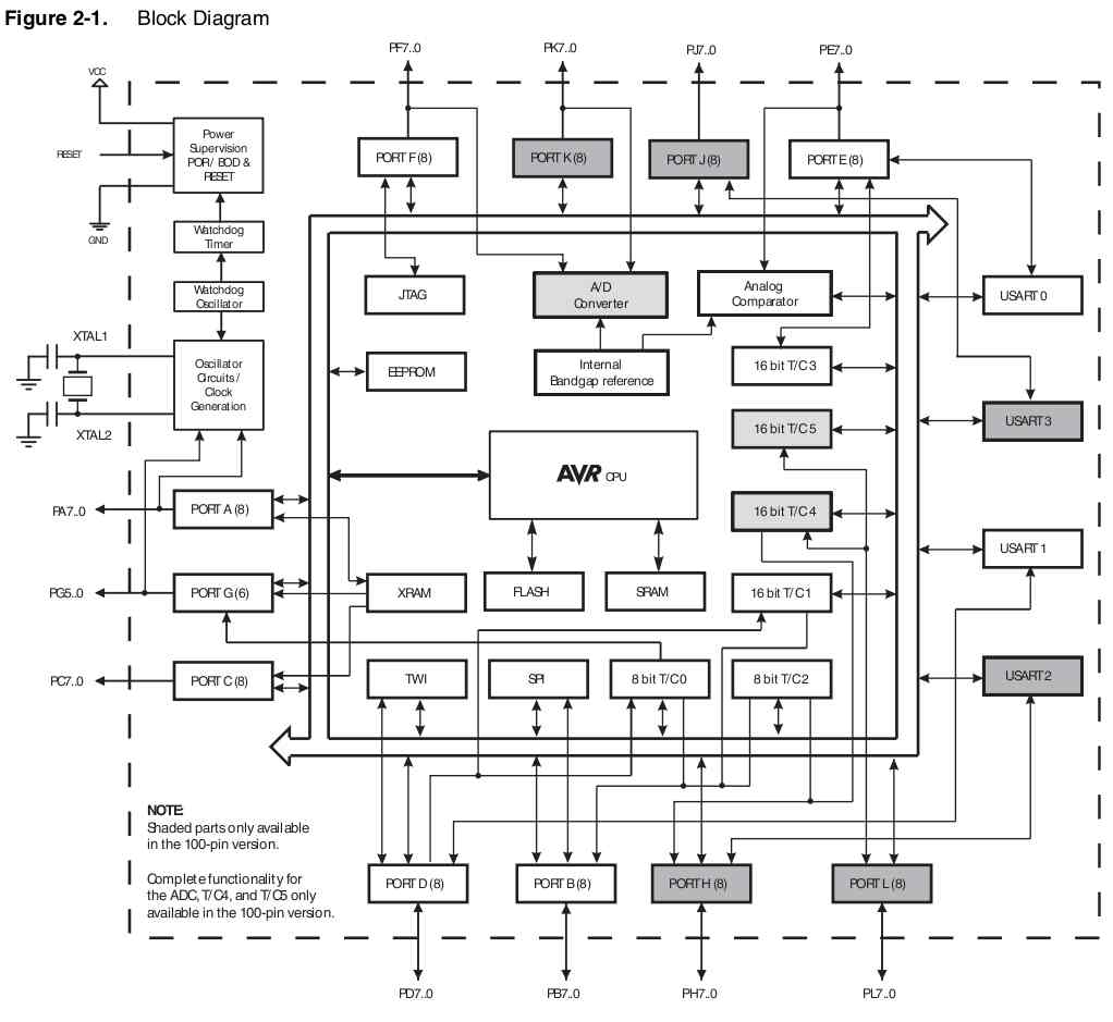
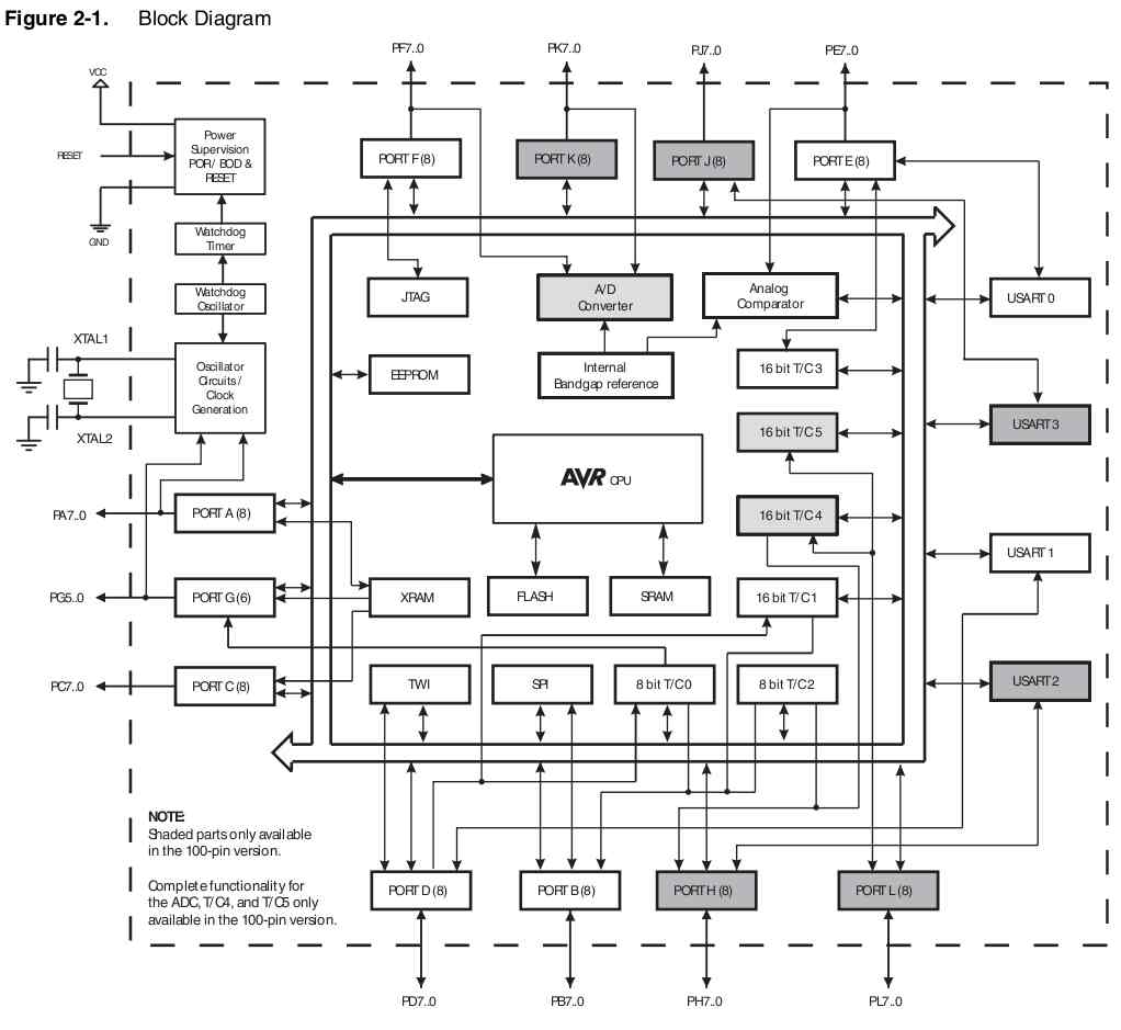
processor (Atmel ATmega2560) does not having built in hardware floating point
math unlike your PC. It does have lots and lots of I/O however unlike your PC :)
See the attached block diagram. One of these days we will find something
that has it all :)
I have loaded Kevin's code into a doc editor and generated a doc file
so the code does not get macerated each time it goes through the
internet. Spaces and carriage returns are meaningful. To compile
it you must remove it from the doc file as plain text. If you
makes changes rename it and keep it in the doc format.
http://arduino.cc/en/Reference/HomePage
Paul Lamar
The Rotary Engine News Letter. Powered by Linux.
ACRE NL web site.
http://www.rotaryeng.net
You Tube
http://tinyurl.com/amz8apm
Copyright 1998-2013 All world wide rights reserved.