I had to go to the SF valley to check out a laser jet tube cutter
and MM welder and stopped off at a Pick a Part junkyard.
I found this GM LS1 mass airflow sensor for $45.
Retails for $399.95.
Took me five minutes to get it out of the wrecked Isusu truck.
All it took was 2 screw drivers a phillips and a straight :)
"Mass air induction systems measure airflow with an electronic
"hot-wire"
type mass airflow sensor. The sensing element in the air intake
provides an
output voltage reading that is directly proportional to the amount
of air
that is entering the engine. This airflow measurement reduces the
calculations required to control fuel and ignition spark advance. Mass
airflow sensors can react quickly and accurately to sudden changes in
airflow."
Usually it is 0 to 5 volts. I will use this with the Arduino program
and a slide throttle on the RV4.
They are easy to locate and mount as you put them upstream from
the slide throttle in 2.75 inch ID hose.
Paul Lamar
Hi Paul, The early types had a circuit that at switch off the wire
was heated to burn off any gunge sticking to the wire and cleaned up the
wire for next time engine was started. Hard to see the $400 value in
those things.
John Burey.
You can buy new ones made from plastic here for $100.
http://secure.ultracart.com/__catalog/PSI/ACCESSORIES/MAF-__Sensors/ACC-1004.html
<http://secure.ultracart.com/catalog/PSI/ACCESSORIES/MAF-Sensors/ACC-1004.html>
Connectors called pig tails here:
http://secure.ultracart.com/__catalog/PSI/PIGTAIL-__EXTENSIONS/LS-Vortec-Pigtails/__PIG-1019.html
<http://secure.ultracart.com/catalog/PSI/PIGTAIL-EXTENSIONS/LS-Vortec-Pigtails/PIG-1019.html>
While searching for a schematic for the LS1 MAF I ran across this
explanation
of the advantages of putting the injectors at the upstream end of the
p-port runner tubes.
http://www.hotrod.com/__techarticles/engine/hrdp_9812___10_common_efi_mistakes/__viewall.html
<http://www.hotrod.com/techarticles/engine/hrdp_9812_10_common_efi_mistakes/viewall.html>
"Carbureted and throttle-body fuel systems are considered wet flow.
Port EFI
designs (an individual injector for each cylinder) are referred to as dry
flow. In a wet-flow system, a mixture of air and fuel coarses through the
intake-manifold runners; in port systems, the fuel is administered at the
end of the intake-manifold runner just prior to entry into the cylinder
head. The laws of physics dictate that for every 10 degrees Fahrenheit of
change in the temperature of the charge, there will be a corresponding
effect of 1 percent to the specific output of the engine-raising the
charge
air temperature will decrease power; cooling it will have the opposite
effect. Wet-flow manifolds enjoy the advantage of cooler charge air
temperatures created by the vaporization of the fuel. When changing
from a
liquid to a gaseous state, this transformation will consume some of
the heat
from the intake tract. Dry-flow manifolds do not benefit from the latent
heat of vaporization."
"The results of this phenomenon cause fuel-injected engines to be
affected
more by higher ambient temperatures and under hood heat."
"The best-running EFI cars breathe cold air from a ram-air kit."
------------------------------__-----------------
Kevin's Arduino EFI code (attached) does not have a mass air flow
sensor input.
It works like Tracy's code on intake manifold pressure and air
temperature
correction I think. I suspect a mass air flow sensor would simplify
the code some what and most important the look up table.
In any event the 5 wire version of this mass air flow sensor has
a temp sensor for $2 more. A real bargain.
Paul Lamar
What about redundancy with a MAF sensor? Can you run two of them in a row?
Everett Rankin
I don't see why not.
BTW I think one might be able to do away with the math in the EFI
program speeding it up greatly. Mass airflow changes with temperature
so no need to calculate the mass flow from intake man pressure
and intake air temp.
Paul Lamar
You are right Paul, I use the temp and manifold pressure to determine the
pulse width, along with an input from the adjustment pot. I have ordered
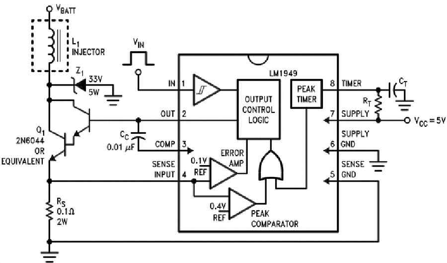
some LM1949 injector driver chips and will start the driver board as soon as
they get here. My injectors are the tan 550s with low impedance. Research
says these are peak and hold, and this driver chip is specifically designed
to run this type of injector.
As far as the MAF sensor, you may be correct that the MAF would be simpler
code wise, and if we used both MAP and MAF either could be used to calculate
the injector PW- giving redundancy. I like redundancy makes me feel much
better.
I have tested several triggers for the coil, and while researching I found a
schematic that is used on an older Rx when changing the old coils for the
J109 units. Many of these old cars are converted to 2nd gen CAS and coils,
have no ECM, and run. I built this unit, and while it did work it didn't
work as expected it did work. The schematic calls for the output to be
pulled off of the 2nd NPN transistor, but I couldn't get the coil to fire
there. At the listed coil trigger contact the voltage goes -5v. At the
first transistor (from the 7805) it is 5v positive, and is interrupted every
time there is a trigger from the CAS. Anyway, it worked pulling the trigger
from the output of the first transistor.
I found some places in my original code that need adjustment, and am working
on the changes. I will send them to you as soon as I get it fixed. My plan
is to have the whole thing done within a week of my driver chips getting
here and run a full system check with the CAS, coils, injectors, etc. so I
can get it installed in the plane.
After this works, I will add in the code for the sort of cruise control I
mentioned earlier. I have been working on the logic, and I think it will
not be too difficult, but I want a working system before I start adding to
it.
My eventual system will consist of 2 Mega boards, and 2 of the Uno R3s. I
like the digital temp sensor but it seems to want a delay built in to get it
to work. The problem is that when you use the delay function, the whole
system stops for the time period of the delay. The default for the digital
sensor is 750 ms, way too long for our purposes. So, I plan to unload all
of the sensors to the third board and just export the output to the main
processor boards. I will build in a default closed loop setting and fault
indicator to let you know something went wrong and you might want to
consider landing in the near future. In the interest of redundancy, the
system will be able to run off of either main and either uno. The total
cost will be under $300 I think. And after this works, I will use a
bluetooth output from the boards to send the monitoring data to a tablet.
I found something today that I think you guys may can use- it will be in
another thread.
I will keep you up on my progress.
Kevin Alderman
Henry suggested exporting the look up table in comma deliminated .csv form
so it can be edited with a spread sheet and shared with others.
The peak and hold injectors have disappeared. Most are now high impedance.
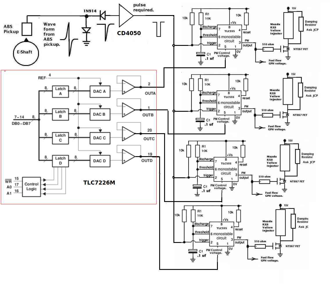
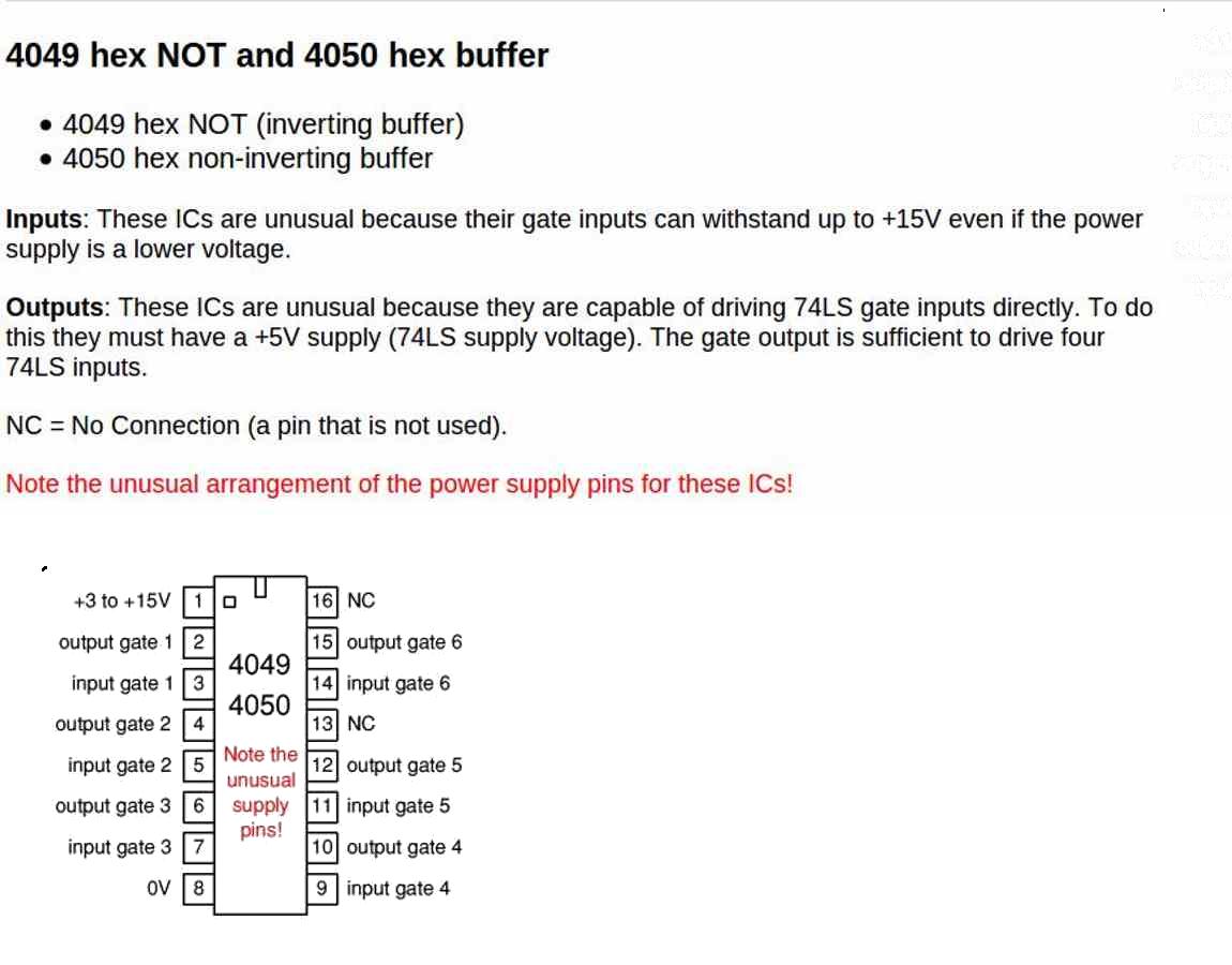
For digital amps you can't beat a hex CMOS 4050. Amps can be paralleled
to get up to several hundred mill amps. Try it you will love it.
Another analog cheap chip I have found to be very useful and versatile
is the: ULN2002A, ULN2003A, ULN2003AI, ULN2004A ULQ2003A, ULQ2004A
See the attached pdf.
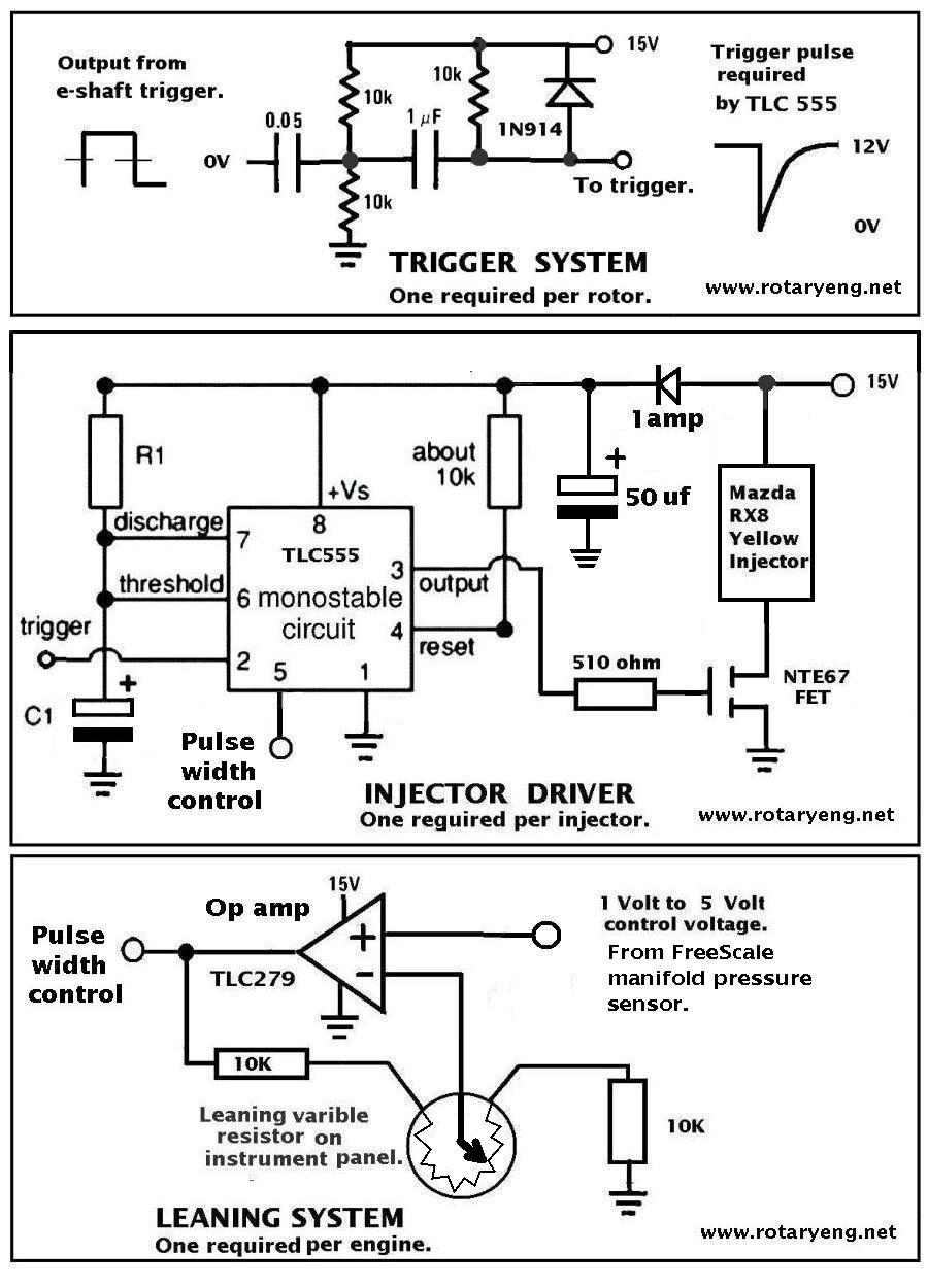
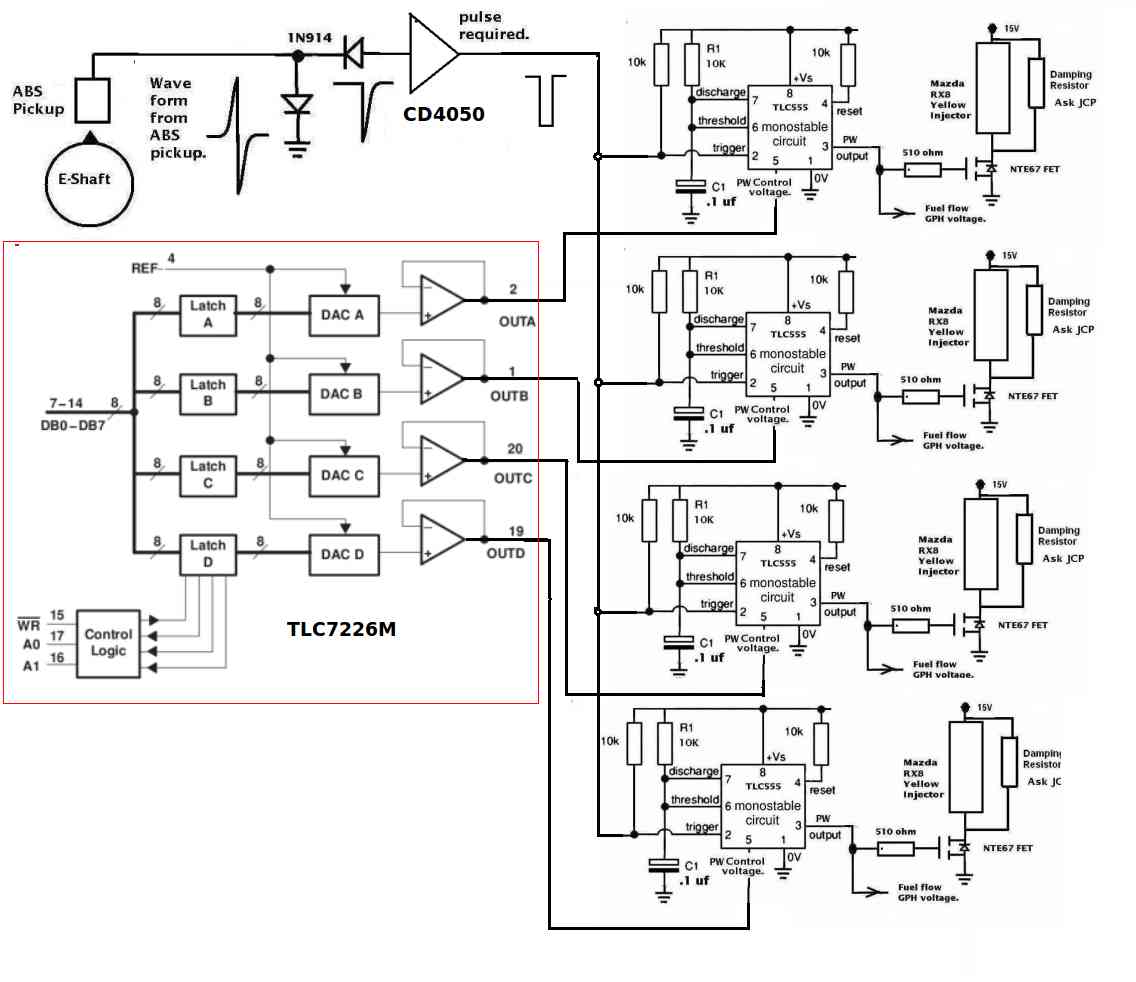
To save the valuable CPU timers and pulse width software a $1 CMOS 555
when fed with a D to A can give pulse widths over a wide range and drive
a FET injector driver directly.
Paul Lamar
The Rotary Engine News Letter. Powered by Linux.
ACRE NL web site.
http://www.rotaryeng.net
You Tube
http://tinyurl.com/amz8apm
Copyright 1998-2013 All world wide rights reserved.