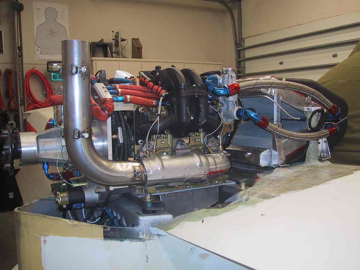
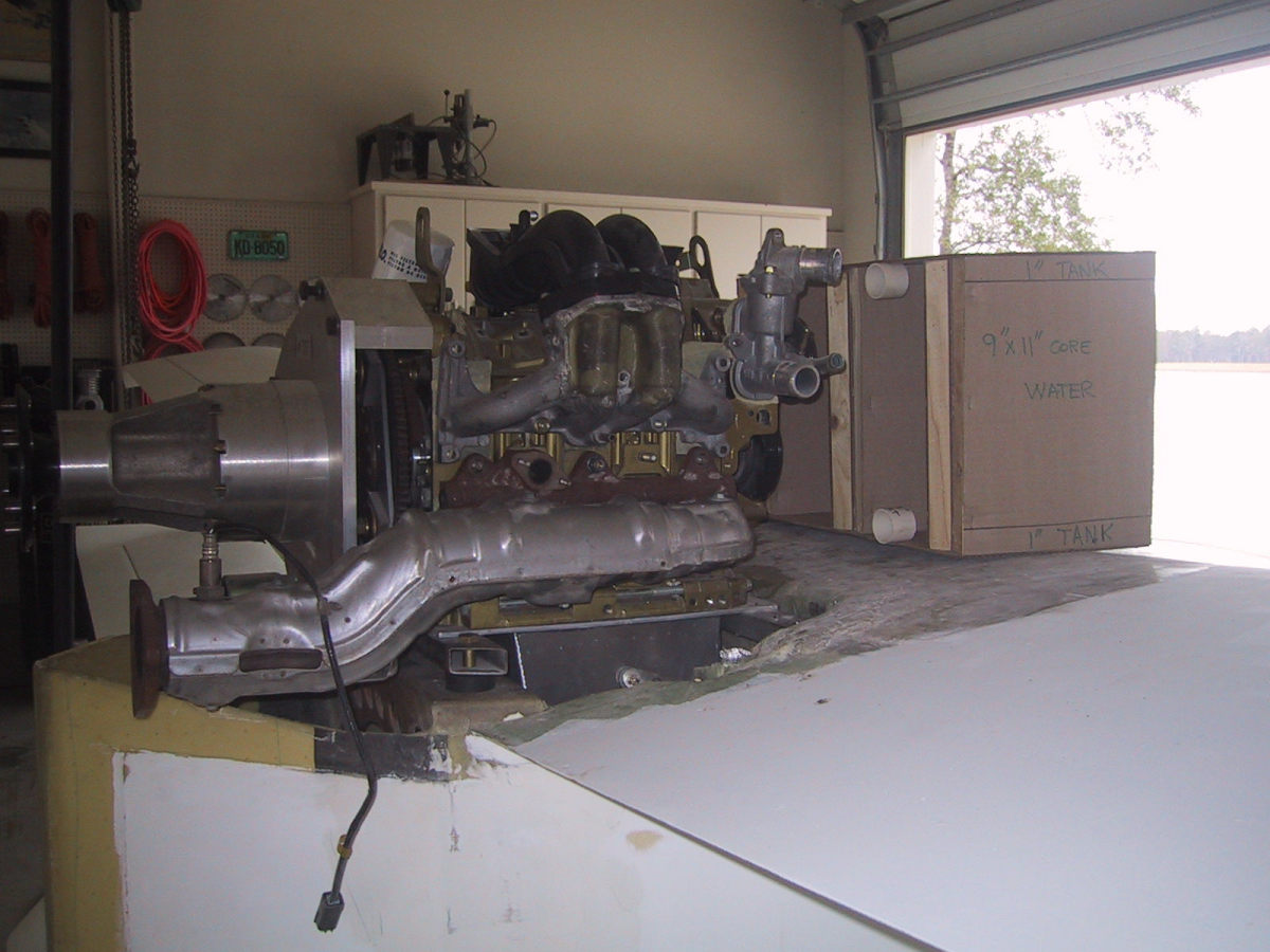
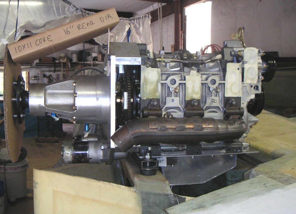
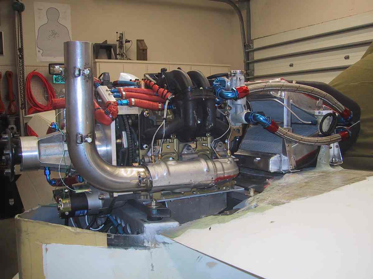
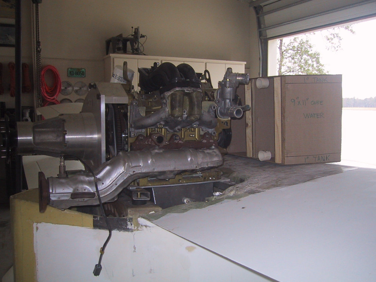
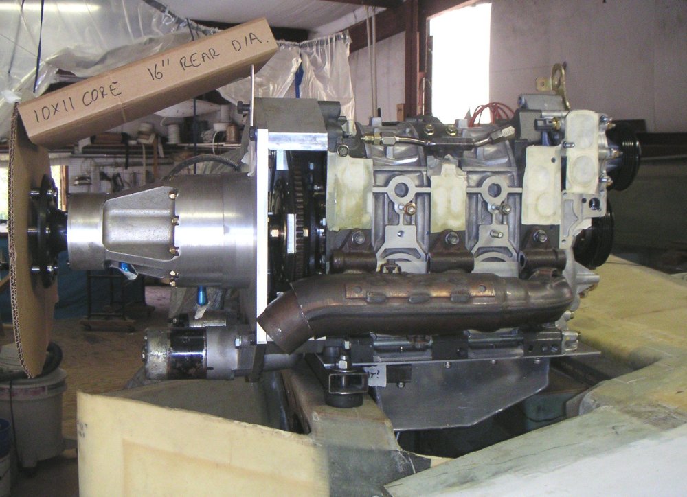
engine pictures.
frank clementi
Nice work on the motor plate.
The front motor mounts are going along for a ride :)
The rear motor mounts are taking 90% of the load.
That is because the CG of engine,GB and prop combo is just
about inline with the rear motor mounts.
You only need three. "A structure will be statically indeterminate
whenever it is held by more supports than are required to maintain
its equilibrium."
In mechanical engineering it is called redundant constraint. Google it :)
The front rubber bushing can be real small as the load on it is near zero.
Please try just attaching those pictures to your email Frank.
Don't ship them off to some web site.
Many emails add's do not accept zip files.
Paul Lamar
Paul,
These pic's are old ones, the engine is currently sitting
on the engine stand. I'll forward those as soon as I
resolve sending pic's. I not sure of whats going on yet.
Now, as far as the C.G. of the engine is concerned, if you
notice the chains supporting the engine in one of the pic's,
are centered above the joint between the number two
rotor and the rear cast-iron housing. That's about 5 inches
forward (remember, this is a pusher) of the rear mount's.
I'm guessing that after the extension and the prop, the
C.G. should be about in the middle of the rear housing.
That will be about 65%-35% (rear-front).
Frank
Yes. That is about right for the CG.
But you could move the bushings further forward :)
We used to use a short schertz beam under the rear housing
but we killed two birds with one stone and saved
a bunch of weight moving the bushings to the motor plate.
Those side rails are real pretty but you would save a lot of
weight with a schertz beam :)
Paul Lamar
The Rotary Engine News Letter. Powered by Linux.
ACRE NL web site.
http://www.rotaryeng.net
You Tube key word PaulLamar2
Copyright 1998-2013 All world wide rights reserved.