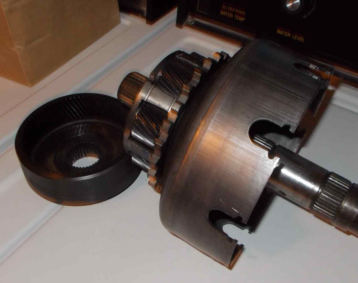
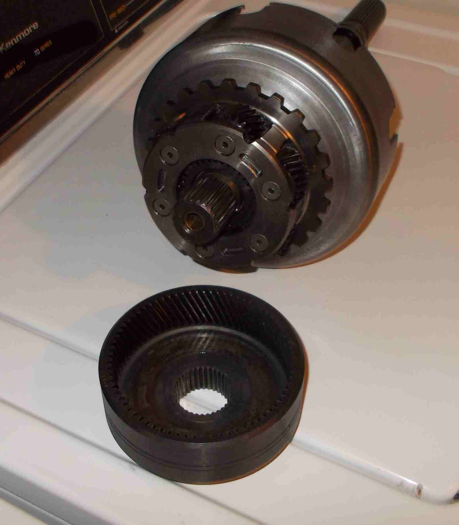
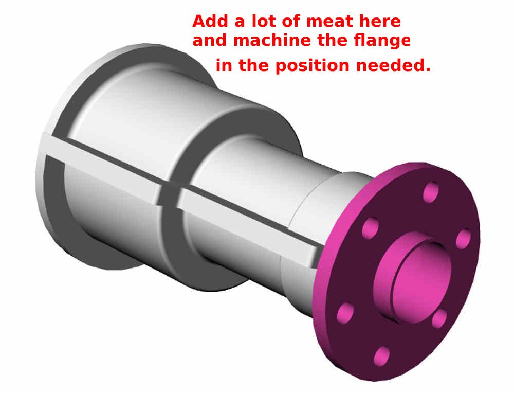
Paul, crank shaft finally arrived.
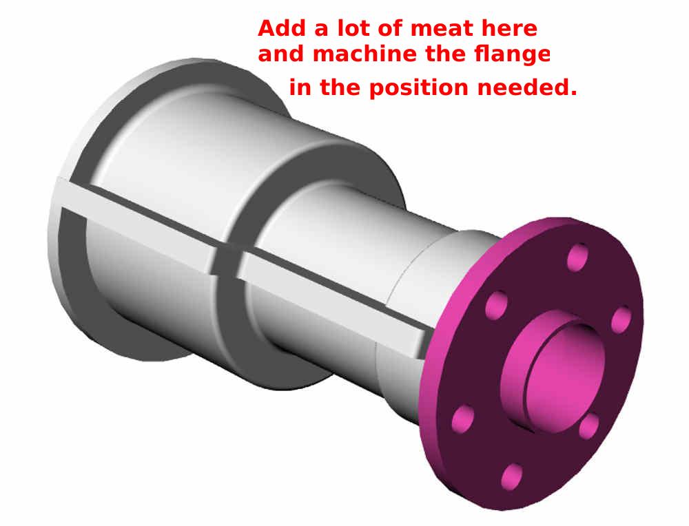
I need guidance on how to trim this, and specific dimension for the plug
that goes on the end of the crankshaft, length of the shaft, to support the
thrust needle bearings, needle bearing part numbers, etc. I would like to
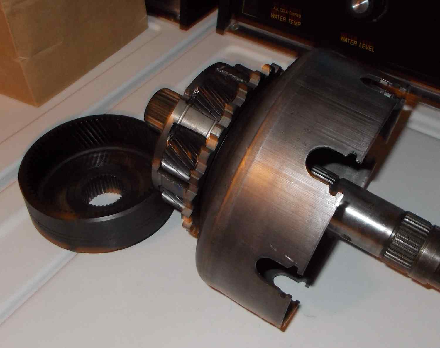
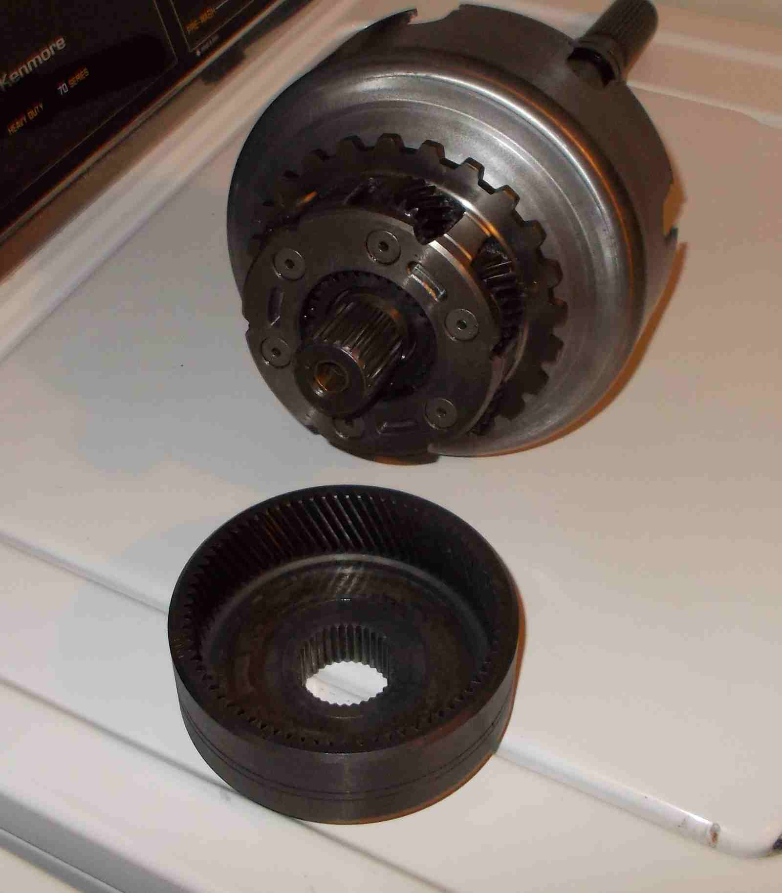
plan for the simplest and lightest drive combination using the attached
methods for the first shot, have another crankshaft piece in bound for the
second shot. Milo
ROBERT speak to me, I need that clutch plate NOW. Any
body know Robert help me contact him.
Paul,
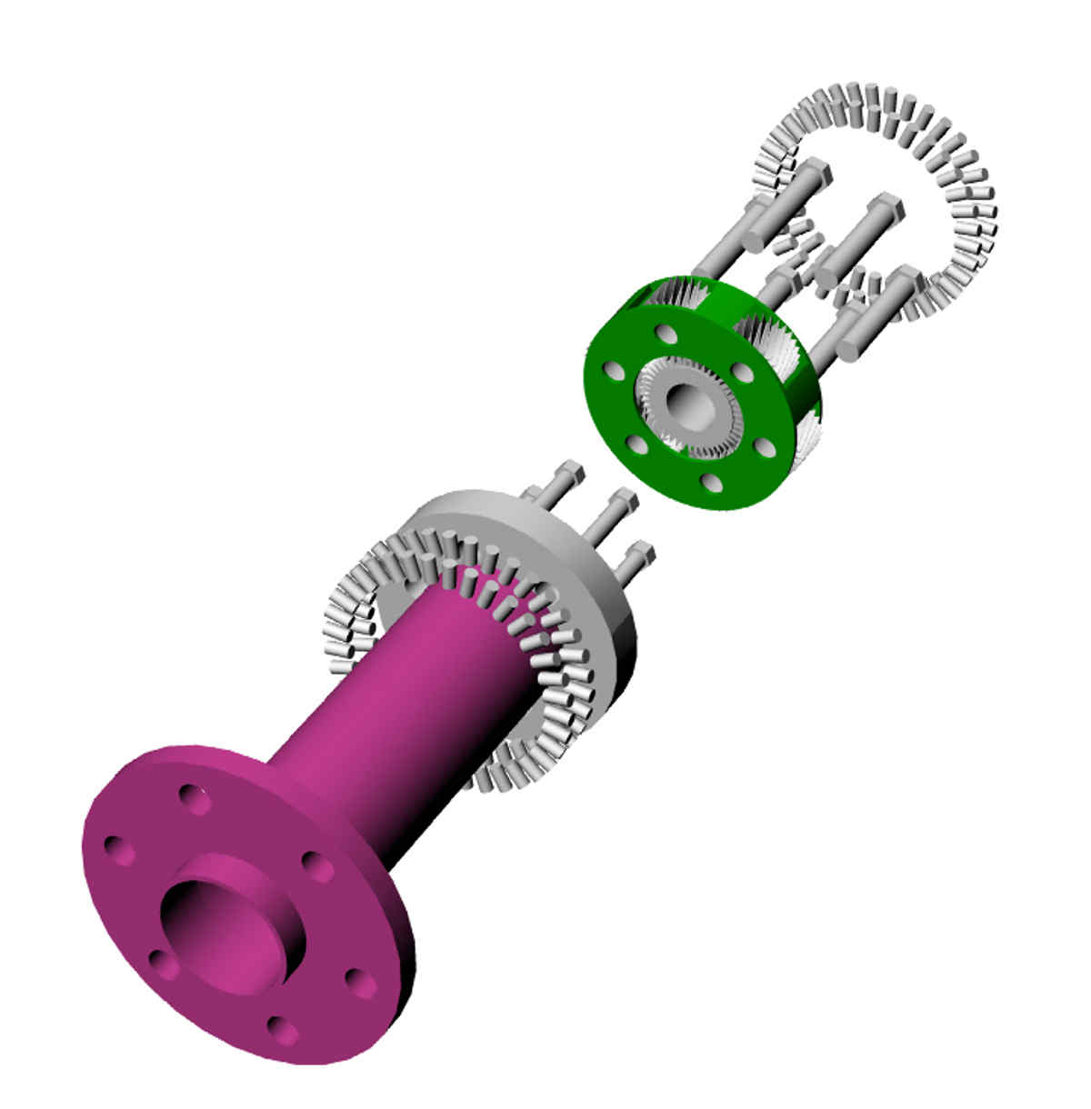
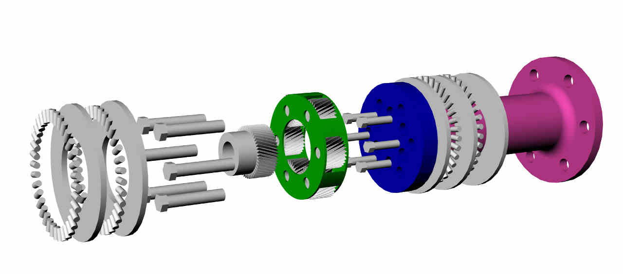
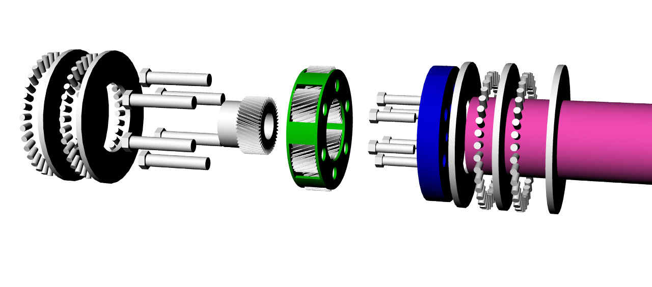
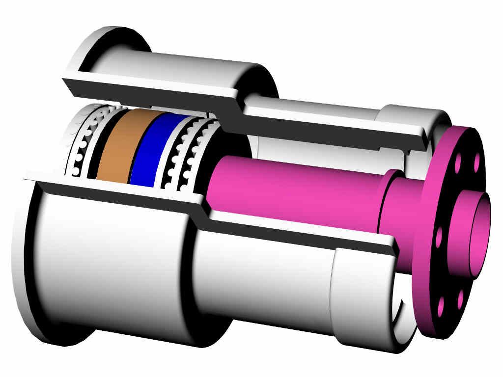
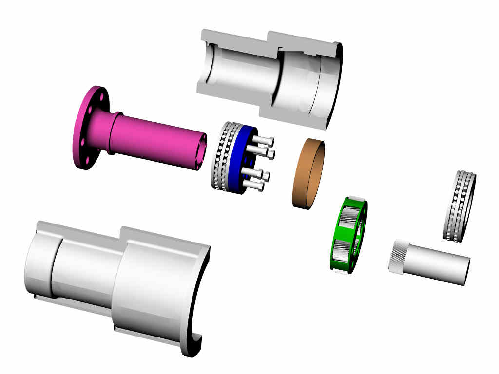
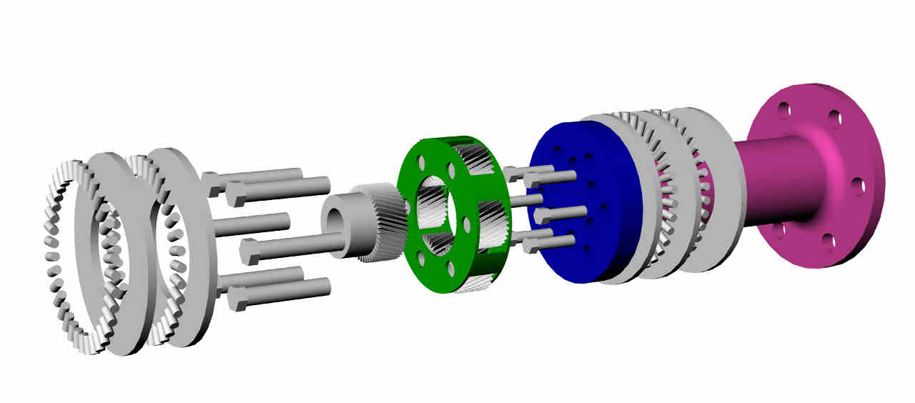
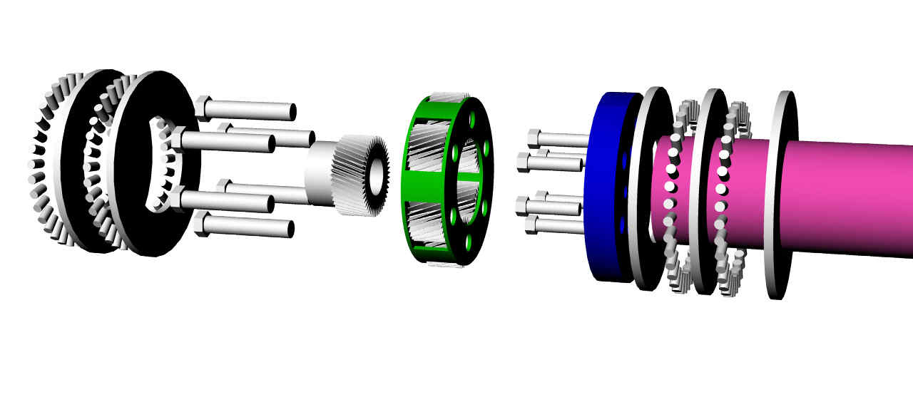
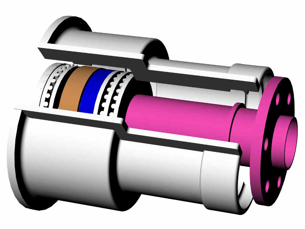
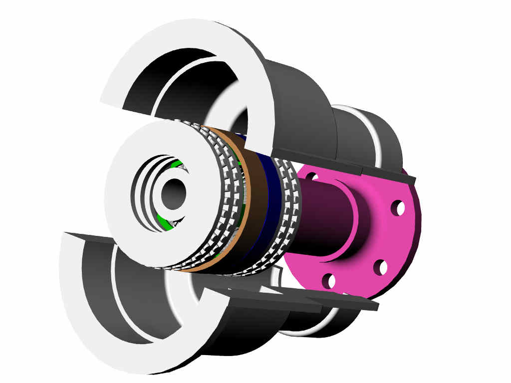
In the colored cutaway picture of your new design psru (middle picture)
there are several short pink cylindrical shapes that appear to be extensions
of the planet gear shafts, visible between the aft end of the planet set and
the aft thrust bearing. May I ask what they represent?....perhaps bolt
heads that connect the planet carrier to the prop shaft? Also, I am
wondering about exactly what contacts what at that aft end of your psru...
does the front (forward) surface of the planet carrier cage simply contact
the aft surface of the thrust bearings directly? If those pink lugs ARE
bolt heads, can THEY also contact the aft thrust bearings directly? If not,
it might be tricky to achieve contact with the aft thrust bearing. Thanks
again.
Gene Kahn
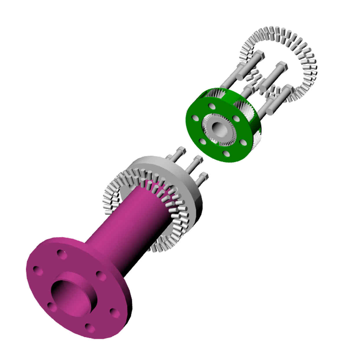
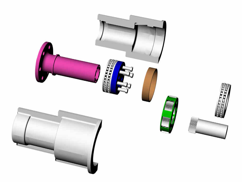
Those represent the heads of the 5/16 bolts holding the planet
carrier to the output shaft. It will also need a small dowel pin or two
for absolute alignment.
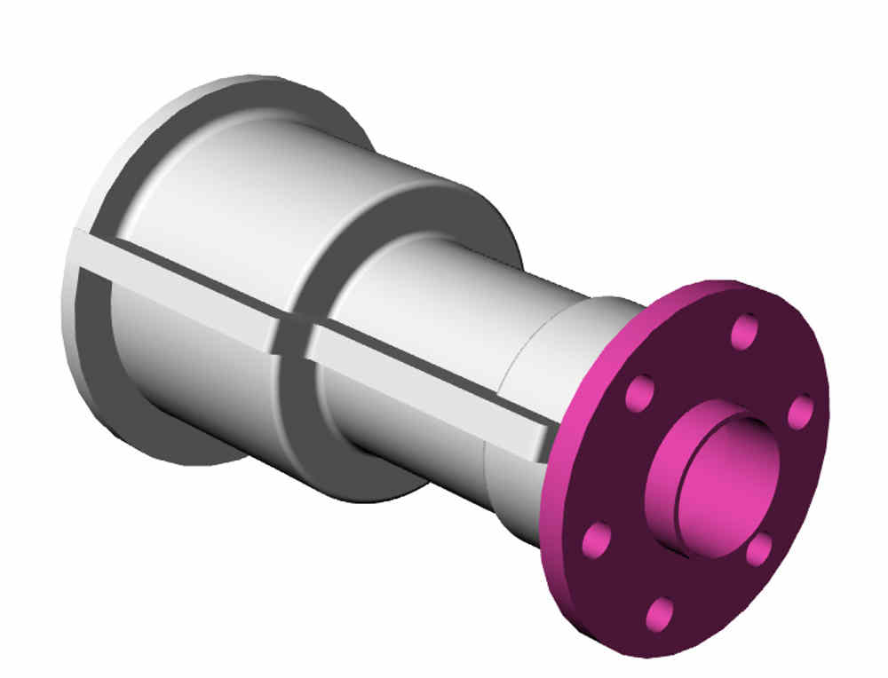
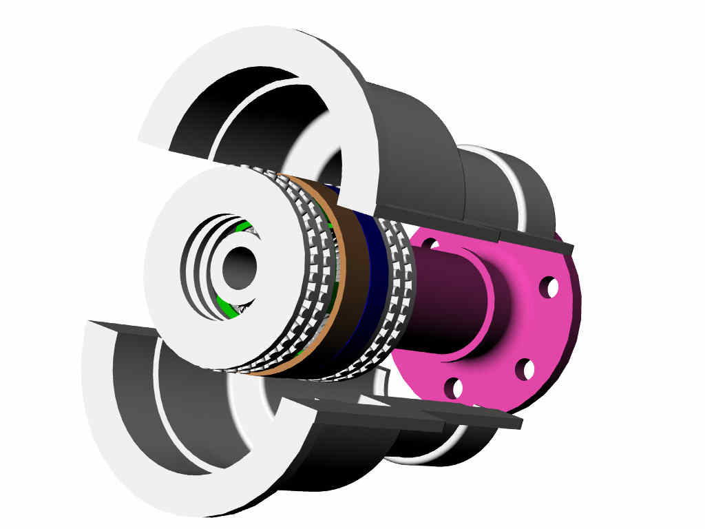
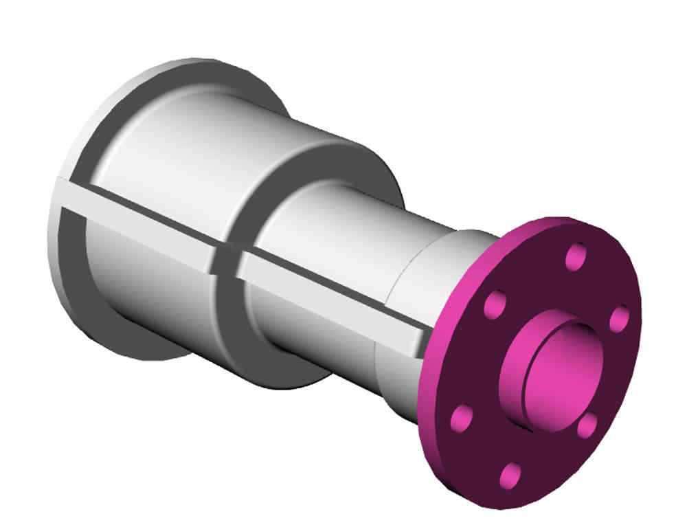
The one piece housing shown here is not going to work as
the stock Lyc bearing shell needs crush.
This is what works.
Paul Lamar
The Rotary Engine News Letter. Powered by Linux.
ACRE NL web site.
http://www.rotaryeng.net
You Tube
http://tinyurl.com/beqqxas
Copyright 1998-2013 All world wide rights reserved.