Paul and others,
1.Is there a relatively easy way to enter a parametric curve
intoRhino?Specifically, the parametric curve for the epitrochoid housing?
2.When you show threads on the bolts in your drawings, are
thosethreads of a particular pitch and cut? If so, how does one enter
thatin Rhino?
3.When you show gear teeth on the gears in yours drawings, arethose
teeth of a particular tooth profile?If so, how does one enterthat in
Rhino?
Many thanks,
Tom Sash
1.I am not that familiar yet with 4 to know if that is possible.
I don't have 5. Ask Rhino head quarters support.
Could be "Select profile curves".
2. I use the "helix" command and then loft the two curves.
I also cheat and download bolt 3D IGES from McMaster Carr :)
It would be nice if Rhino did threads automatically.
3. So far if you want a particular profile you have to plot the curves
manually in the front view. Then use a Polar array to get a frontview of
gear. Then trim any overlapping lines. Then join all the teeth
curvestogether.
Now you have a front 2D view of the gear.
Then extrude the curve in the top view to make a straight cut gear.
If you want a helical gear copy the front 2D curve to the back side
ofthe gear,
rotate it the proper amount and loft the two curves.
It would be nice if Rhino did gears automatically.
Cheat and download the gear 3D IGES from Arrow Gear soon to be
available.
They have 2D DXF's. You can try importing that and extrude or loft.
I have been doing biz with Arrow Gear for the last 45 years.
I was working as an engineer for Craig Breedlove on this wheel driven
land speed record car and Arrow supplied the final drive gears.
Later to become the Rocket Car.
Paul Lamar
Paul, how does that front suspension work?I don't understand what the
swingarm pivots on for steering.
It is called a virtual pivot. Where the two lines drawn through the axis
of the two horizontal links converge forms the vertical pivot axis.
The links form a virtual pivot ahead of the tire contact patch so it
forms a caster effect.
Here is an example of such a system on my flying motor cycle design.
The two vertical links control the camber of the wheel and the lateral
link mounted at the back of the wheel controls the steer angle.
Craig said it worked very well up to 400 MPH.
http://www.rotaryeng.net/__roadable.html <http://www.rotaryeng.net/roadable.html>
"The two down tubes control the camber of the front wheel as it turns
left or right. The pivot axis is a virtual axis formed at the
convergence of the lateral links and the upper convergence of the down
links. Since they are parallel they converge at infinity in outer
space some place so the pivot axis is near vertical. To add rake angle
or caster to the pivot axis you move the top ball joint in towards
each other which makes them converge at a finite distance above the
fuselage. The yoke is made out of half a dozen layers of carbon fiber.
Craig's was made from thick wall square steel tubing. The link below
and in back of the yoke is the steering link. The steering box and
steering arm are not shown. Nor are the pneumatic cylinders that
support the suspension on the road and retract the front wheel in
flight. Nor are the various required suspension attach brackets shown."
"The aluminum links and aluminum ball joints are all stock sprint car
parts. I was at the Ventura dirt track on Saturday night when my 73
year old friend John Richards was racing his 650 HP sprint car in the
senior's race. Dirt track sprint cars take a lot of abuse. That is
where I got the idea for the light weight suspension links. Almost all
sprint car suspension parts are aluminum and very reasonably priced
because of the volume manufacturing."
"The rational for this design is it widely distributes the suspension
loads into the structure unlike a traditional motor cycle fork design.
Therefore it is much lighter than a motor cycle fork arrangement."
Paul Lamar
That is damn clever, the retract setup would work great for an amphibian
too.
Everett Rankin
Thanks.
These pictures are of my friend Herb Adams concept of a front wheel suspension
for a combo flying boat, airplane and car. The V8 lump will never fly :)
Mine is much lighter.
Paul Lamar
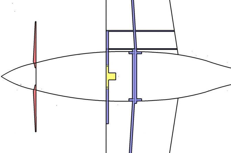
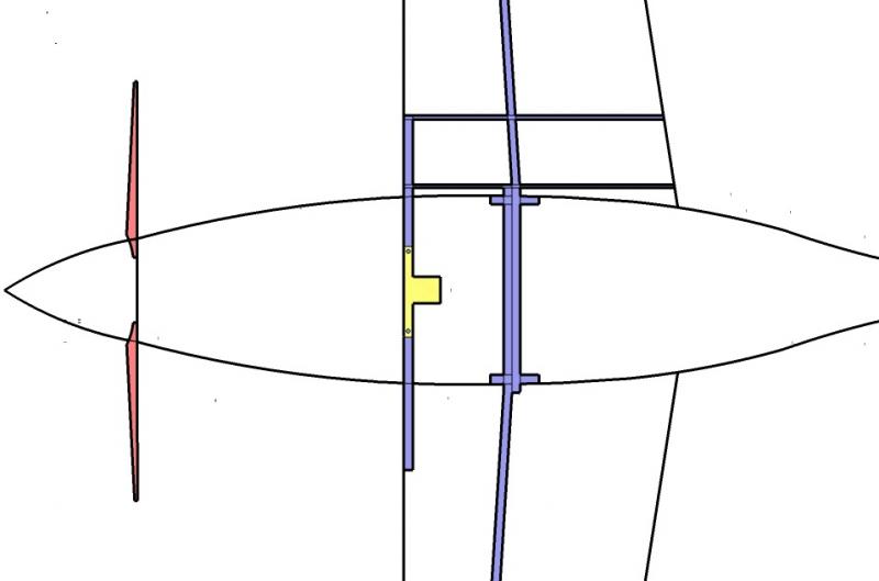
Paul, On your roadable aircraft rendering I was wondering if you have a plan for the attachment of the removable
winglets to main wing structure. I am
building a corrugated spar main wing and hot wired foam winglets and need them
removable to fit in a shipping container.
george grimes
I will probably use the standard sail plane trick of overlapping spars.
Paul Lamar
The Rotary Engine News Letter. Powered by Linux.
ACRE NL web site.
http://www.rotaryeng.net
You Tube
http://tinyurl.com/beqqxas
Copyright 1998-2013 All world wide rights reserved.