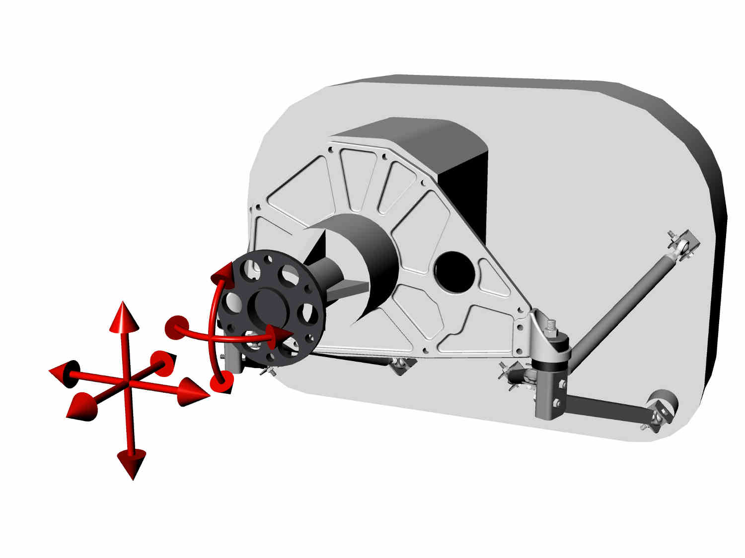
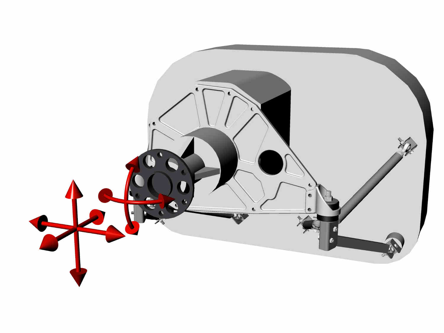
One of the features of our new low cost universal motor mount I
am working on is there are four tubes that need ball joint
adapters tig welded to the ends. Eight joints per motor mount.
This is easy to do for a skilled tig welder but it is like
riding a unicycle while juggling for me. I can get a functional
joint but it is far from cosmetic. I have to stop...weld about
30 degrees.... stop.... rotate the tube 30 degrees and do
another 30 degrees.
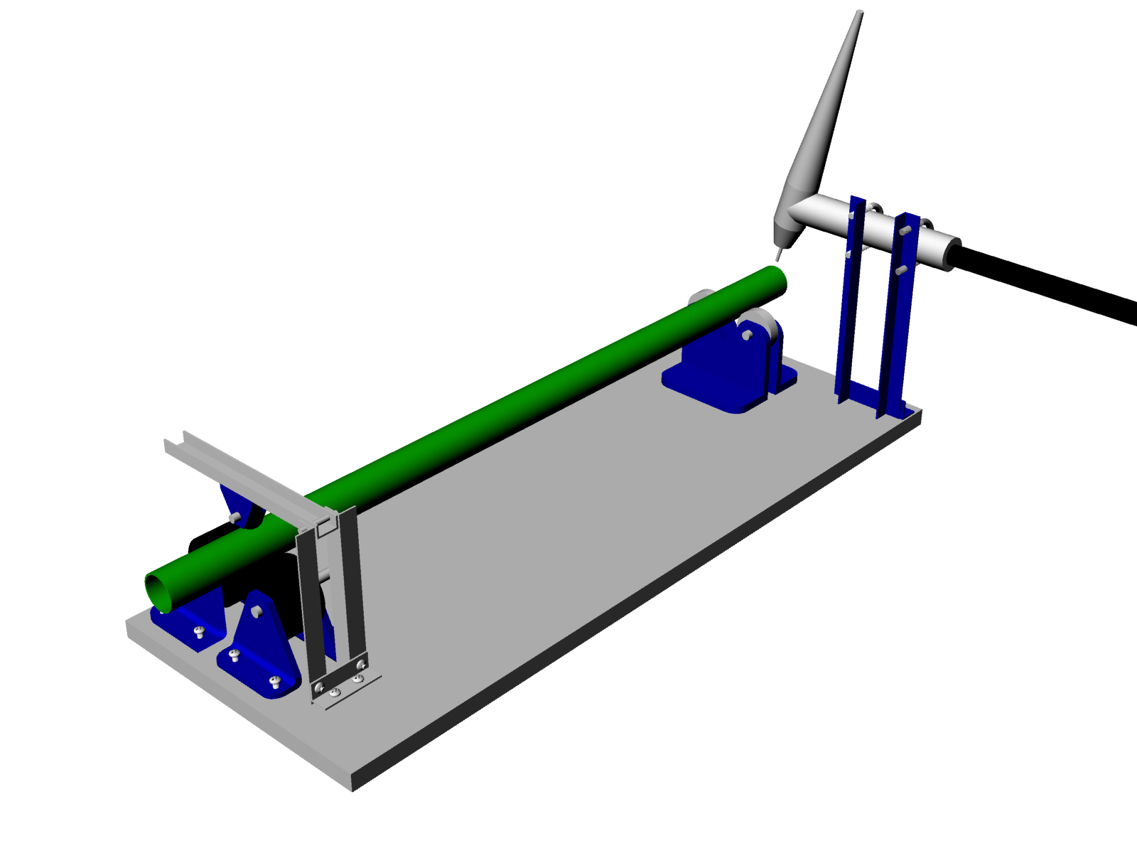
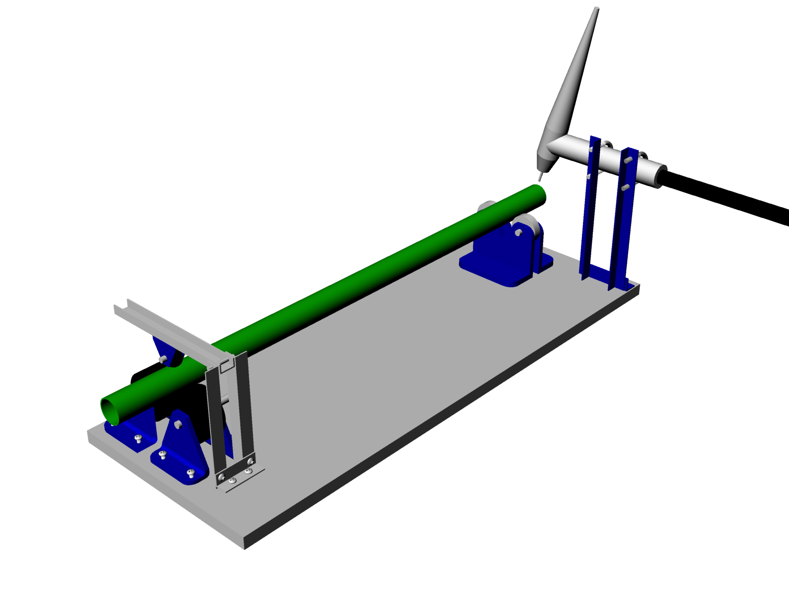
There must be another way so I am building a robo welder just for this
job. I'll offer it as a service because it only takes a few minutes for
each joint.
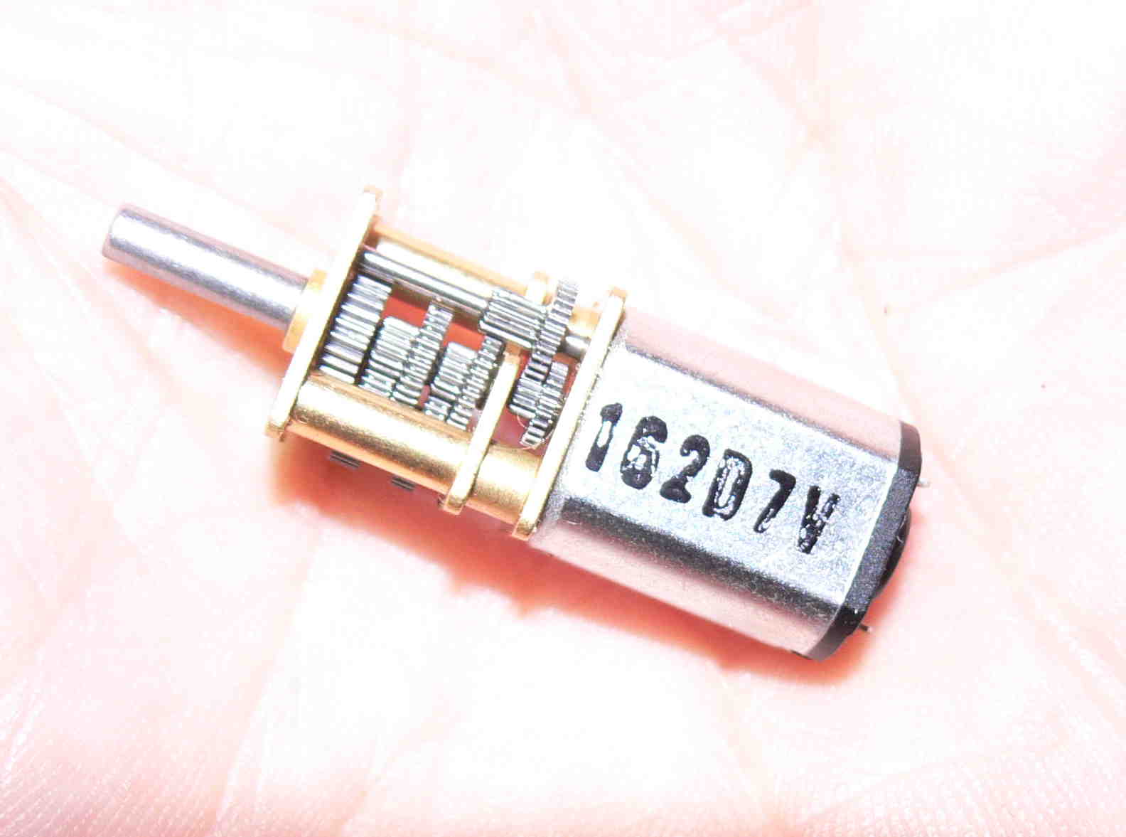
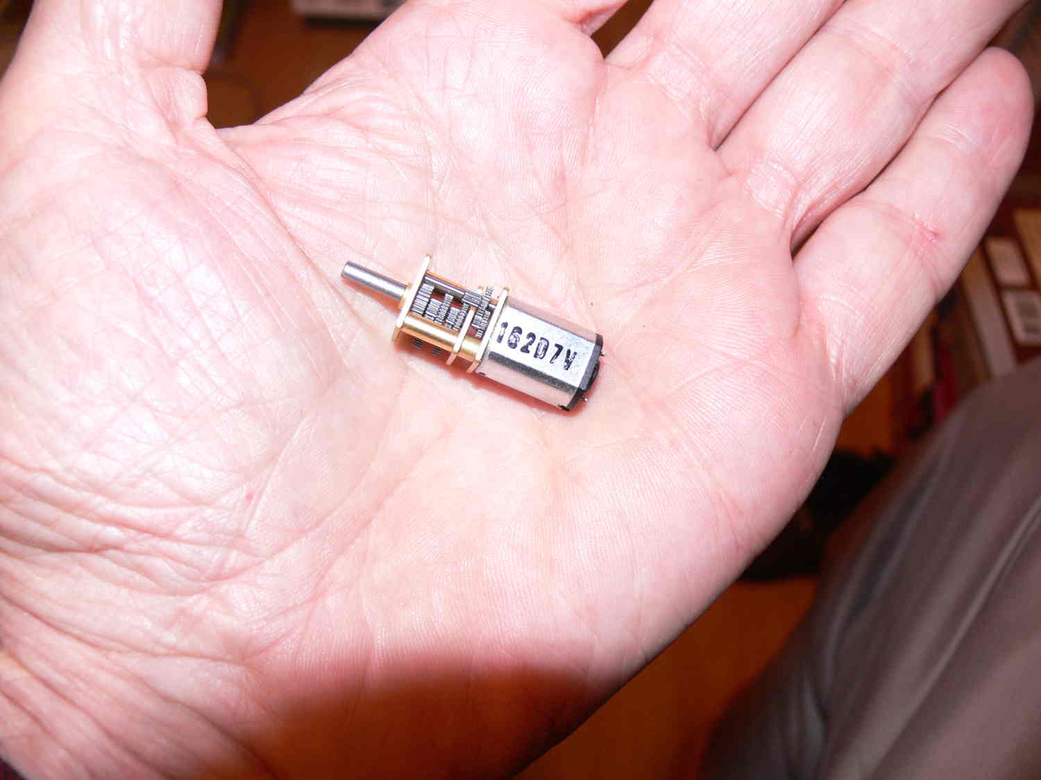
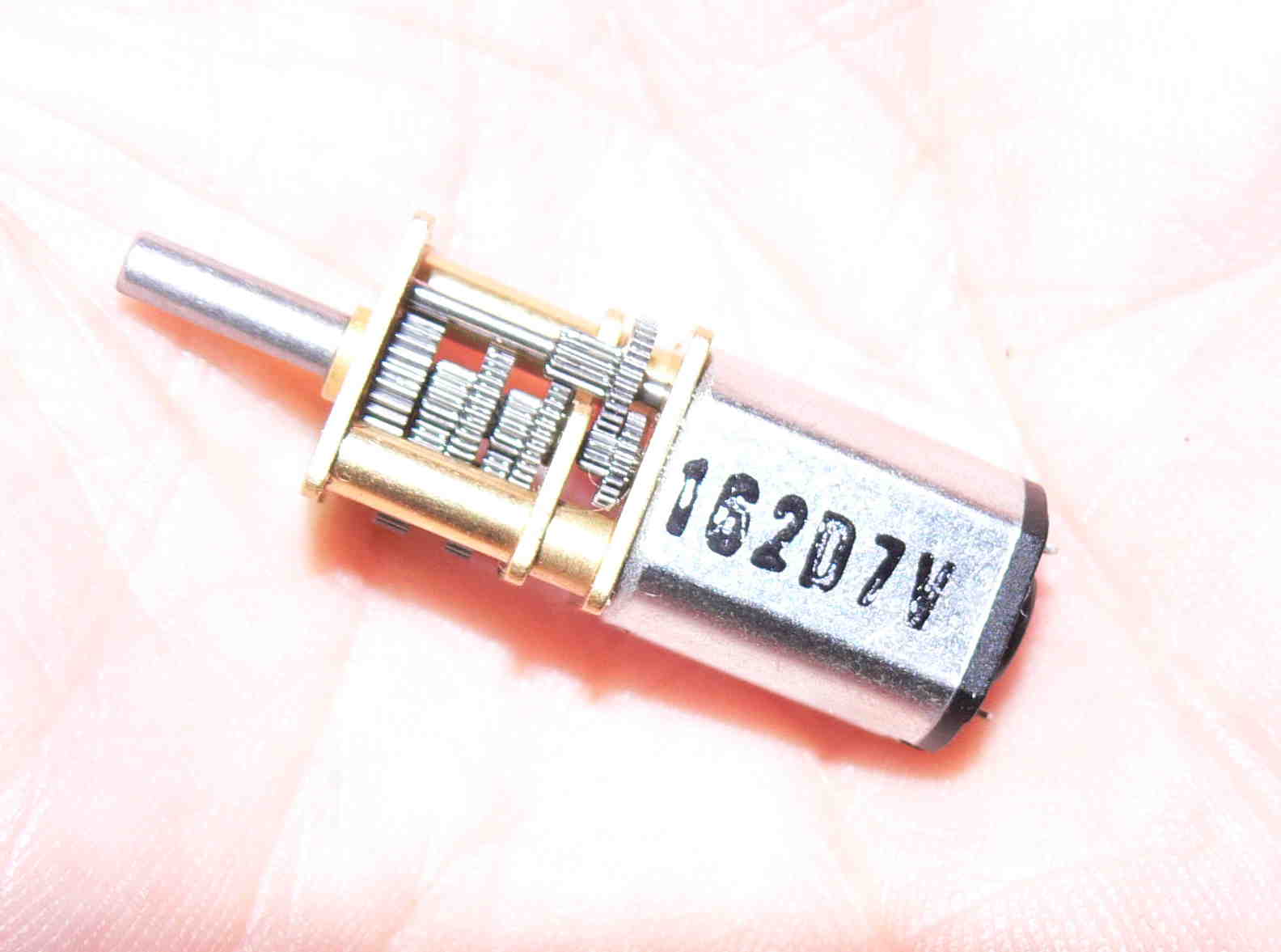
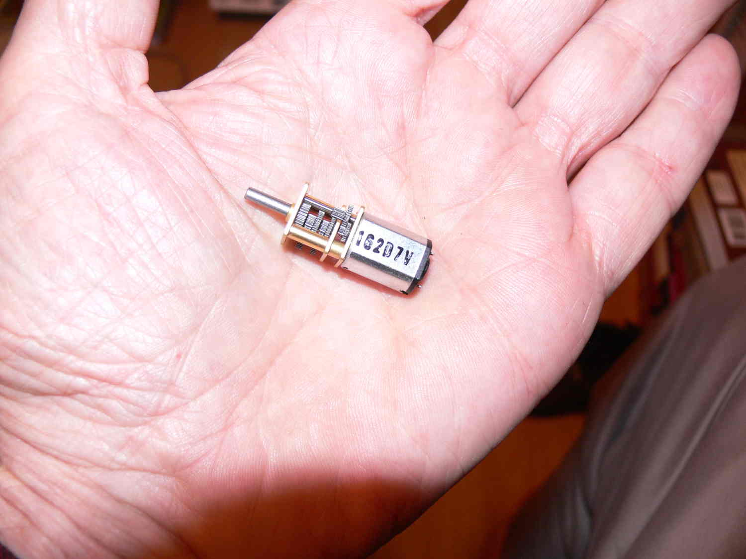
Pololu $22 gear motor has a 1000:1 gear reduction so it is
slowly rotating the the tube at a constant rate. You just need
to come up with the correct distance for the tungsten and the
right welding current and gas flow. The rest is automatic with
my Lincoln 175 tig I bought at Sun N Fun on sale.
The rollers that turns the tube are plastic as you don't won't 80 amps
flowing through the gear motor. There would be a spectacular fire with a
pool of liquid metal :)
Paul Lamar
Paul,I built one of these years ago to do boring welding at
our shop like putting hubs on gears or the end of a tank.I
don't think you want to have your ground dragging on the part as
it will leave arc pits as it conducts.I put a pointed vertical
shaft (1-7/16") into a grounded carbon block.Mounted the shaft
in two brass bushing sleeves under a 4' square table.There was
a 20" circular work table the part set on with some adjustable
centering blocks like a lathe chuck.I turned the shaft with a
variable speed 3/8" drill with the trigger locked on and running
thru a rheostat from a wire feeder as used on our MIG welders.
The drill turned a 100:1 gearbox and had roller chain drive to
the vertical shaft with about a 4:1?sprocket ratio.I have a
cover that closed everything inside for smoke control with a
large welding lens in the cover and a hand hold hole to set and
adjust the tig or mig gun while it runs for irregular shaped
parts.It welds 1" to 20" diameters with the same drive
sprocket and could do much larger with more sprocket reduction.
This rig welded thousands of parts with only the drill motor
brushes being replaced a couple of times.I also built one like
your sketch to weld headers shafts, and caps on roll case
rollers.There was a sleeve that slipped over the end of the
shaft for the ground clamp and it just twisted the ground cable
360 degrees to weld the part.That machine was used but not as
trouble free as the vertical one.
The big problem was the work
walking along the support rollers end wise.That was patched by
tilting the rig a few degrees and having an adjustable end stop
on the opposite end of the welding.The plastic rollers
(UHMW-green) didn't drive worth a crap.Real irregular feed and
stop and start while welding.I changed to steel wheels and put
a third weighted wheel on top at the drive set.It then worked
well but seemed like more trouble than it was worth.
We
continued using it but should have built something else.If
you like the vertical spindle you could have a threaded stub
sticking up to screw your weld bushing on and slide the tube on
till the shoulder of the sleeve.One other thing, I had a limit
switch to stop the rotation at exactly one revolution.The
start button bypassed the NC limit switch and started the welder
thru a 3 pole glass relay.The limit switch unlatches the relay
to stop.An idec solid state timer left the welder run a second
or so while the motor coasted to a stop to overlap the end of
the weld over the start point.These things did a wonderful job
with shield gas and flux core MIG welder but it is really hard
to get tig set up.A SS guide sleeve for the filler will aim it
but an operator must work the wire in and out to apply it.A
really tedious job.
george grimes
Thanks for the tips George. I'll let you know how it goes.
Paul Lamar
I took your advice on the tilting to locate the tube longitudinally.
I also decided to feed the current in from the other end of the tube
which will also serve as the metal stop you mentioned. Any pitting
can be sanded off.
I realized I had to make it adjustable if I were feeding the current
in from the other end.
The length of the tubes varies by up to a foot or so.
Paul Lamar
Paul there is a spray can variety of nozzle anit spatter for MIG
welder nozzles that you can spray your machine with everyfew parts to
keep spatter from sticking to things like the support roller
slide rods.
george grimes
I don't notice a lot of spatter with the tig.
Just in case I'll get some.
Thanks for the help. There will be a third iteration :)
I'll move the stop rather then the torch.
Paul Lamar
Your not going to believe this George.
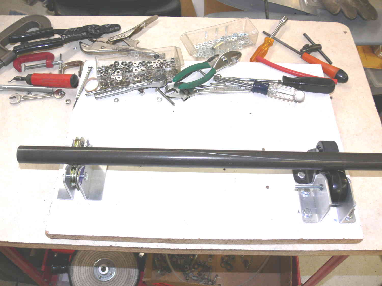
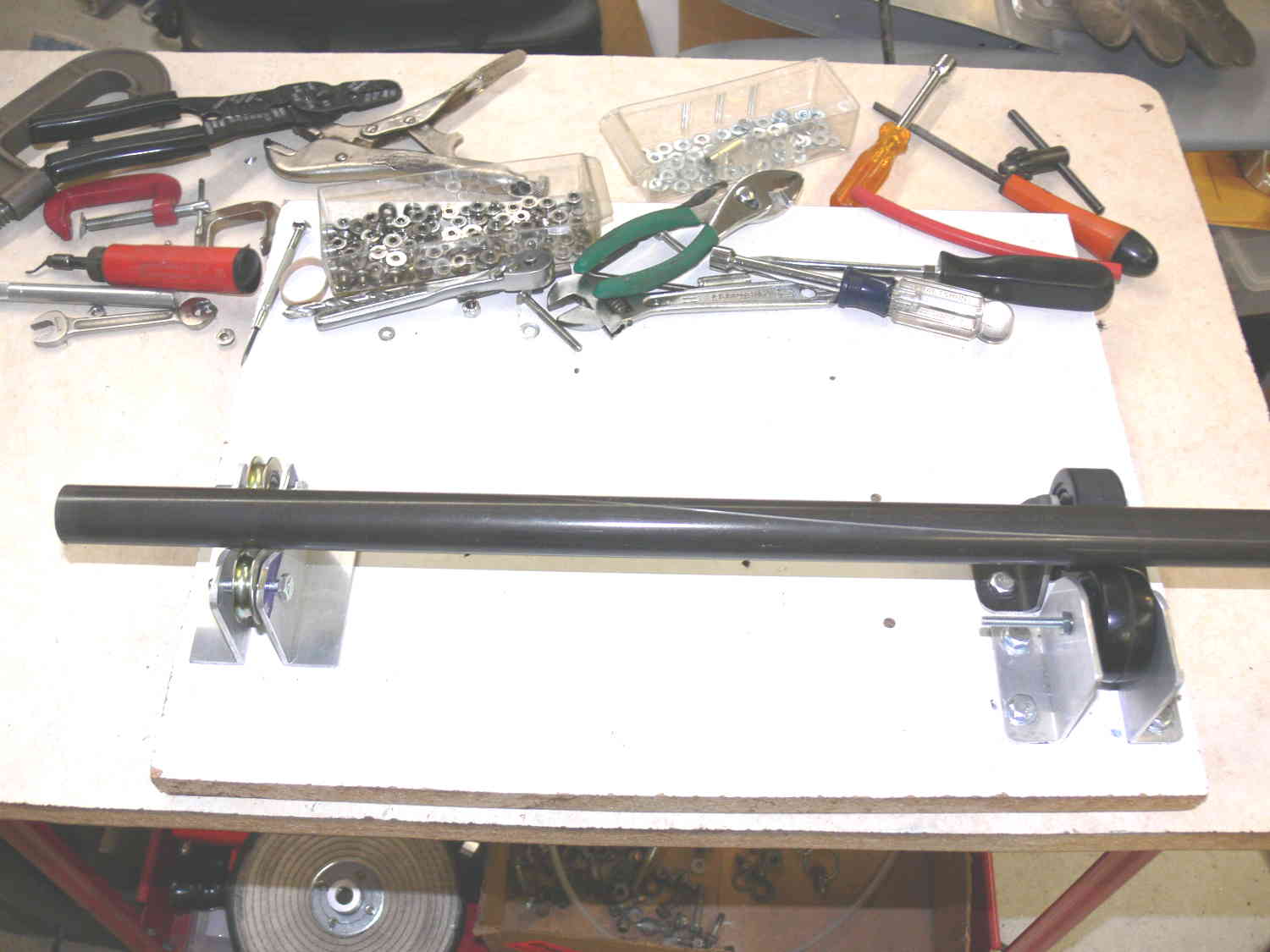
Here is my complete drive for rotating a one inch steel tube and one
rev per minute. Classic trade off for torque verses HP.
It does not take much HP to rotate the tube at one RPM.
The gear reduction here is one thousand to one.
This device does this at .5 volt in and 10 milliamp's.
The motor is rated up to 14.7 volts. God only knows the torque :)
It is possible to destroy this gear box by stalling the out put
so I am using a short piece of rubber hose to couple it to the drive
roller. All rotors use miniature ball bearings. The 2 near the torch
are screen door rollers. The stop is not shown. The stop will ground
the tube.
Paul Lamar
to see how fast it turns. I raced 1/24 scale slot cars until
the rental tracks all disappeared. The Globe motors turned
30,000 RPM before I rewound them for more RPM. The flat can
motors only have two magnets and don't turn quite as fast.
These motors at minimum voltage have a "lumpy" output RPM which
goes away with more RPM. Slot car controllers are supposed to
be 0 to 14 volts on a 12 volt track. Looking at your drawing
the support/drive wheels appear to be bigger diameter than the
tube which will rotate the tube faster. This may be a good
thing. 1" X 3.14 = 3.14" per revolution.
That is not a lot of
surface speed if the welder is set high enough to get the insert
up to the melting point. My Miller TIG has a start function
that boosts the welding voltage at the start and tapers off so
the foot pedal control is less tedious to use. You might need
to have the tube rotation ramp up to speed as well. A side
benefit is that the surface speed will be the same if you stick
a 1-1/4" tube in your rig, and if the same wall thickness the
welder will also be set.
george
Don't need to do that. I have an expensive power supply that measures
the current to the nearest ma and has variable voltage to the nearest
.001 volt. It runs on .5 volts and turns one rev per MINUTE.
I am only doing one inch tube.
Paul Lamar
I spent a lot of time on one of the rollers made from a black plastic
caster wheels. I pressed a 5/16" steel spacer into the center of the
roller. The spacer had a 10-32 bolt passing through it and then into
small ball bearings in the support angle brackets.
I drilled the first spacer on my lathe and the 3/16" hole came through
at a slight angle. The roller wobbled. I asked my next door,
professional machinist hangar neighbor, Jim Poole to make me one his
better lathe with the same unfortunate result.
I then had him make another one drilling from each end. That worked.
Smooth as silk. That took the entire afternoon. It is slowing me down
from making the first motor mount. The metal rollers near the torch end
are sliding door rollers and they work trouble free. So far I have about
three days in this thing but it will be well worth it for low cost motor
mounts.
The motor mount will be adjustable in all directions and all side and
down thrust angles.
Very helpful when you are trying to get the prop flange to come out in
the center of an existing cowl hole.
Paul Lamar