Paul,
That's exactly how mine looks. But the actual sealing area of the
seal is back into the counter-bore so that it just misses the
splines. From the picture, and looking into the flywheel area (fully
assembled), it appears the splines go into the seal, possibly keeping
it from doing the job.
Mark
On Sun, Jun 9, 2013 at 6:05 PM, rotaryeng <
rotaryeng@earthlink.net
wrote:
The aluminum billet version was getting expensive. The material
alone was $66. I know I just bought some today. I had to pay $16
just to have it cut to lenght.
Then I was having trouble finding suitable 10 mm 1 mm pitch metric
screws. I never found any I was completely satisfied with. Making
our own was getting expensive.
The welded version can use the stock 10 mm 1 mm pitch bolts as it
is only .125 thick which can replace the stock clamping plate
The light really went on when I thought of welding the walls
directly to the steel spline plate.
No bolts or screws needed to bolt the spline plate to the
coupling. The spline plate is half the coupling.
Nothing could be easier or simpler.
The walls are rectangular .75" by 1.5" 4130 tubing from Aircraft
Spruce. I have some in stock.
There must be only three walls because there are six 10 mm bolts.
Here is what it looks like. It fits the stock 2 rotor flex plate
but does not stress it. All torque is transmitted by the six 10 MM
bolts.
I will weld one up and send it to you for testing Mark.
Paul Lamar
What amazed me is the coincidences. The rectangular tubing just
happened to be the right dimensions. There are only two choice's
from aircraft spruce. 3/4 by 1 1/2 is one of them. This leaves
plenty of room for a couple of needle thrust bearings between the
spline plate and the gear box adapter plate.
BTW asymmetric rubber bushing might work out to be the best
configuration. Most of the rubber on the compression side. The
acid test will be the lowest engine RPM that does not cause
resonance. That does not mean it is not mitigating destructive
torque pulses at higher RPM's. The kind that shear bolts and pins.
Paul Lamar
Carrie Beasely was right. Powdered metal. I won't weld to powdered
metal. Back to 2 pieces 4130 sheet metal. Hard as heck. I ruined a
band saw blade on it. It came with all this stuff inside for $37.
Hack saw in the lathe does not work well.
Schabs Parts 12715 old plank road New Lenox Il 60451
Paul Lamar
This fixes the clitch. New 4130 welded sheet front coupling. The
4130 2.75" OD tube .120" wall clears the big nut and keeps the
rubber from getting chewed up by it.
This is what I will build. No welding to the powdered metal spline
plate. Separate 4130 front coupling weldment.
Paul Lamar
Paul,
That looks good to me. How do you plan on making the silicone
dampers?
If you can get the pieces cut to size and send it all to me, I can
weld it up and then test it.
Mark
No welding on the spline plates. Too risky. New 4130 front part
instead.
I was thinking we could buy fabric reinforced silicone rubber
sheet from McMaster or AC spruce and cut it to shapes. Then glue
them together with red RTV to form crude 3D shapes..
OK I'll do that Mark. I think I have located mild steel tubing of
the right sizes. The tube parts are lightly stressed so you can
weld it to the 4130 parts.
Paul Lamar
Paul,
Sounds fine to me. Will there be holes in the silicone to allow
for compression? I guess what I'll need is a sketch.
Mark
I think the crudeness of the 3D shapes will give the rubber enough
room to expand. Paul Lamar
Paul,
Something I need to add to the mix. My rear psru seal has worked
its way out of its bore more than once resulting in damage to the
seal and loss of oil. The fix I came up with was to install three
button-head screws into the flywheel side of the psru adapter
plate in order to retain the seal. These screws may interfere with
your "stacked bearings" solution to the flex hub adapter. I just
wanted to mention this as a possible problem area as we proceed
with the design. As far as I know, I'm the only one that's had this
problem. So, I'm keeping my fingers crossed on whether or not the
double stacked bearings are necessary, hopefully not.
Mark
They can stay there. The spline plate can be turned down on a
lathe so the spline plate bottoms out the splines short of the
screws and clears the screw heads.
As it is now the seal surface on the input shaft extends back
beyond the lip of the seal to the splines which start some where on
the back side of the adapter plate.
The rubber coupling expansion will tend to reduce the force on the
helical gear thrust bearings.
Forgot the jpgs :)
Paul Lamar
Mark, Next time you have the gear box off please measure the
distance from the lip of the seal to the start of the splines.
Also send some pictures of your helical gear thrust bearings.
We might be able to adjust the spacer to get a few more thousands
seal lip clearance before the start of the splines.
This is what it looks like on the RV4 with the old 2.17:1 gear
box. The splines go into the seal somewhat.
Paul Lamar
We can fix that several ways. Depending on what thrust bearing
you have. If you have needles we can change the thickness of
the spacers. If you have the roller version with out spacers
we can shave off the back side of the sun gear. If you don't have
a lathe you can send it to me.
I am also worried about clearance of the long 1/4 bolt heads
holding the gear box together. The best way to fix that is reduce
the max diameter of the spline plate from 6 inches to 5 inches.
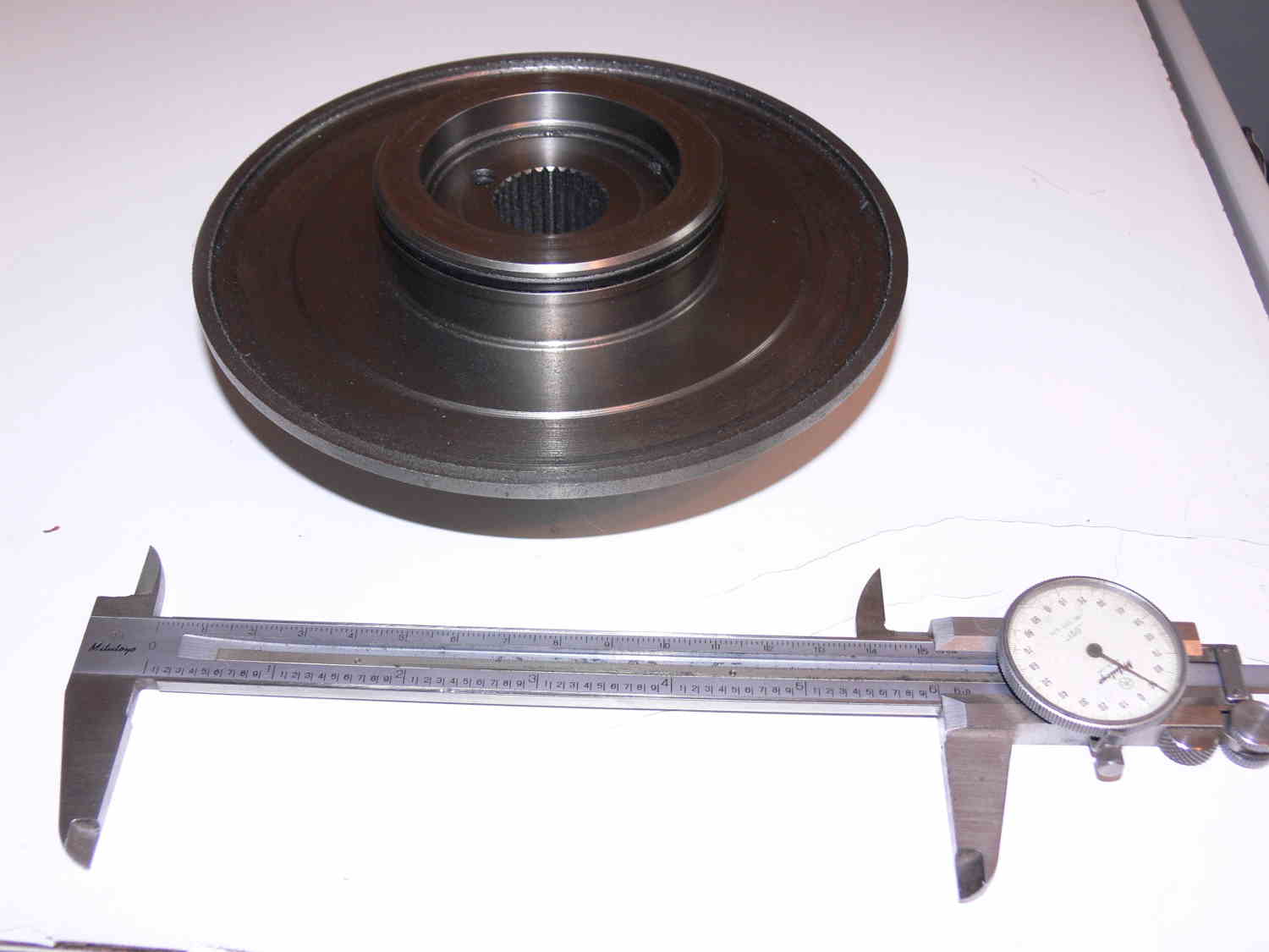
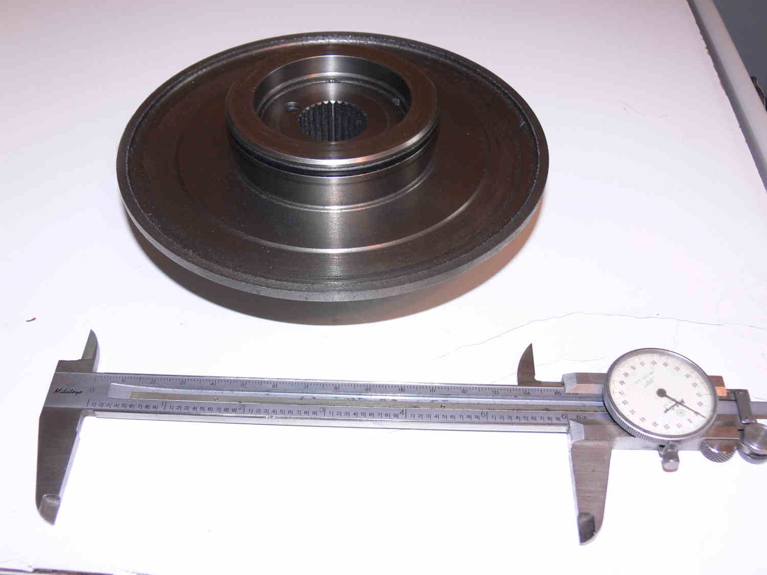
Here is a picture of a new spline plate with just the drums cut off.
We have to machine on it anyway as Tracy does.
Paul Lamar