Paul, (I am not an engineer...nor do I claim anything mechanical
skills.... question for you and the group)
Molt Taylor's Flying Car.... utilized a ??? Centrifugal clutch on
the drive shaft .... with ball bearings (?) About five of them are
still in existence and flying today.........
Why would not a modern version of that clutch work on the Rotary
engine?
Bill ATP
Paul,
Been reading in depth about the rotary VERY interesting engine for
an aircraft. The turbo compounding takes this to the next level.
Barron
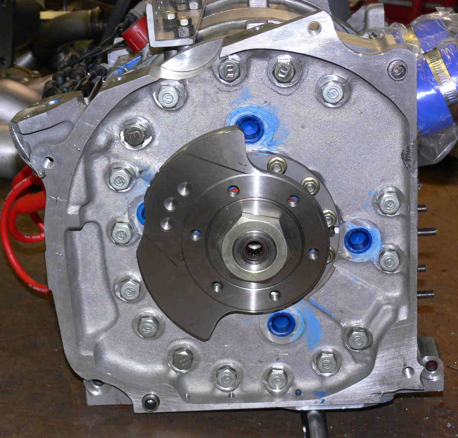
That is my next project. Chris's bell housing put the project over
the top. It eases adapting the DD15 TC system to a 3 rotor.
I was planning on using the Mazdatrix dyno but that would not mate
with Chris's bell housing so I need to build another prop dyno. I
will use one of these ideas.
Paul Lamar
How is the PSRU development going, you could test the new unit
with the turbo-compound and kill two birds with one stone.
Graeme Riley
Paul,
What HP is your psru designed for? Can it handle 350+ hp for
takeoff and 300 hp continuous?
Mark S.
You mean the one Milo is working on? It is based on a recycled six
cylinder lycoming crank shaft. It uses stock Ford six pinion
planetaries.
It has mostly to do with the weight of the prop.
With carbon blades it would be no problem.
Paul Lamar
Paul,
My experience has been that the weak link isn't necessarily the
planets, but something else, like the rivets holding the flex
plate adapter to the hub, or the weld/pin attaching the sun gear to
the input shaft, etc. I was curious as to the design spec for this
box. I know you're trying to keep it light, but there's a limit to
where you are willing to go.
Mark S.
Has anybody pulled down one of Tracy's psru's that has some time
on it. I'm aware of Dave's sun gear issues I was wondering how the
rest of the unit was holding up. Dave did you install a second pin
in the sun gear, If so have you inspected it since? Just curious as
to the results. Graeme Riley
It is showing some weakness in the higher 3 rotor HP levels. The
flex plate is cracking.
IMHO it is due to the lack of an effective torsional damper. In
effect capturing the rubber bushing in an enclosed metal box like
Tracy has done is no damper at all.
They don't work as one might think. If you totally enclose a
rubber bushing (as Tracy has done) it no it longer operates as
rubber. It acts as a solid. Rubber is no more compressible than
hydraulic fluid.
I am building this combo flex plate and damper for the 3 rotor
turbo compound engine I am working on. .090 4130 would be fine for
a 2 rotor. For a 3 rotor p-port or turbo I would use .125" thick
4130
Motor cycle style rubber bushings can be made with red RTV in a
Teflon mold. Good to 500 F.
Paul Lamar
I have been reading about a psru developed for the R1200 bmw
motorcycle engine that is used in aircraft tractor and trike
pusher configuration. It uses a centrifugal clutch like ones in
most chainsaws only much larger, this has solved the torsional
dampening problem. The engines are rated 100-115hp continuous 6300
rpm. The clutch eengauges at 1800 - 2000 rpm and has to be changed
every 400 hrs. These engines have run 2000 hrs in this
configuration. They initially had flywheel cracks when they used
light ones, beefed them up cracks stopped engine ran smoother.
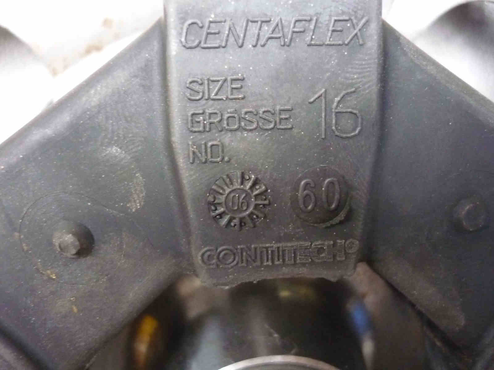
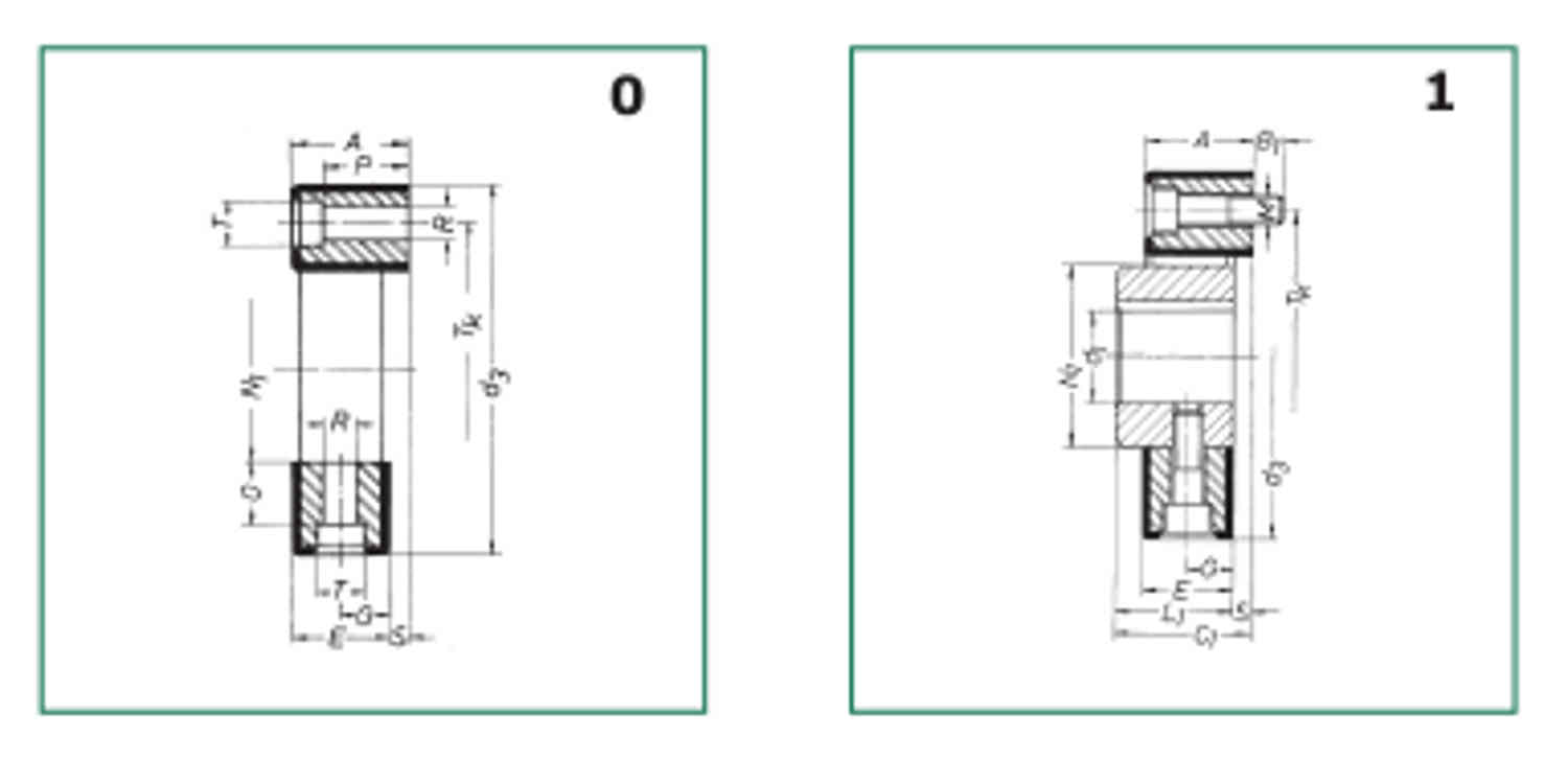
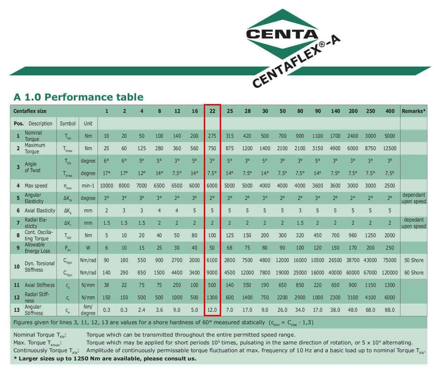
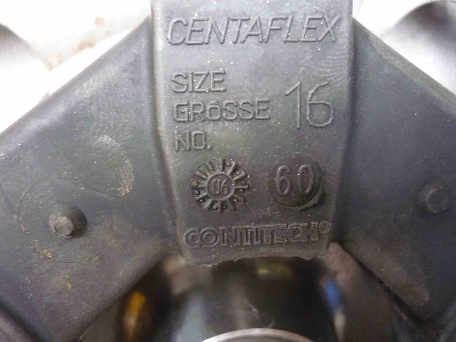
Has anyone considered the rubber coupling used to couple a high hp.
electric motor to air compressors and pumps ect. If i understand
there operation correctly they will absorb energy transmitted back
to the motor and shaft miss alignment between motor and equipment.
I have seen these couplings with several thousand hrs. on them with
no visible wear. Steve Hudson
How high is the HP?
Paul Lamar
Hi. The clutch does not solve the problem as much as avoid it. The
clutch does not engage until the engine is above the resonant speed
of the system. There is sometime a rubber coupling also to bring
the critical point to lower rpm.
http://www.elbe-group.de/presse/download/Folder_Gelenkscheiben_e_low.pdf
Rubber coupling designed for industrial and automotive use, by BMW,
Mercedes. and others. Porsche used one between flywheel and
gearbox on their aircraft engine which was known for its smooth
running if nothing else. Three point engine mounting helped. Also
used by some auto and motorcycle geared PSRUs.
Murry I. Rozansky
I would but when you scale it up for 200 or 300 HP it gets much
larger and heaver.
In the future when one is trying to be helpful think of the space
and weight of what one is suggesting. Get a dwg. of the device and
see if it will fit in a 6 inch dia. cyl. and 1.7 inches long. The
devil is always in the details.
Paul Lamar
Paul, I have been following this thread and have a couple of
questions for you. You point out that rubber does not act the way we
want when constrained. IIRC your damper design uses three
rectangular tubes per side in such a way as they mesh between each
other. This leaves six spaces for rubber dampners. So effectively
your rubbers are constrained by those six tubes and the plates. If
the rubbers fit too tight and you have no dampening, too lose and you
have too much backlash. How do you size and fit the rubbers ? Can
you, do you vary the elasticity of the blocks ? Can you, do you
adjust the shape of the blocks to find a happy balance between
dampening and backlash ? Or do I have the design all buggered up in
my head ?
John Gibbons
The rubbers are not necessarily perfect triangles. They can be any shape.
Feel free to experiment.
Mark S will probably come up with suggestions.
BTW a fabric reinforced silicon rubber cutting tool can be made from
parts of a box cutter blade bolted to a block
of aluminum. Stick the box cutter blade in a vise and break it off to
desiredlenth.
Use an arbor press or drill press to cut the parts.
Paul Lamar
Hey Paul,
I've been watching this discussion going on for quite a while.I've got a suggestion.
See the attached image.
This basic concept can be adapted to fit many different configurations. Essentially the
vibration is taken up by the O rings that fit inside the space between a hole in a plate
or ID of a tube, and the OD of a spool piece that is clamped by bolt pressure between two
heavy flat washers.The rubber pads that fit between the heavy flat washers and the plate
can be made from just about anything for the application you are considering.They could
even be eliminated for your design as long as the spool was 0.010 - 0.020 longer than the
plate is thick or tube is long.
The O rings are not compressed to any great degree when the Dim Mount is assembled
allowing the O rings to compress and expand in response to the vibration. No need for
fancy custom rubber blocks, triangular or otherwise.
With a bit of engineering the whole flywheel, Dim Mount, driven plate, assembly can be
sized to fit in just a couple of inches.
Mark LaPierre
Mark I don't quite follow you on this. Can you expand the dwg to
3 views and show the input shaft and out put shaft.
Also add dimensions.
Paul Lamar
Hi Mark,
Your drawing looks like what Ford does on the flywheel of the 7.3 Diesel.I know because
I've had to change a couple of them.They usually last 250K miles of hard use.When they
fail there is a slight rattle, but the parts are captive and only when an owner really
abuses or ignores it does it make real clatters.Never seen one come apart yet...Check
out the equivalent HP to see if it is in the range.Just sayin
Dan
Dan Hennis
;-)
Dan your real time clock is still broken. It is annoying for me as your
messages come in out of sequence and I might miss them.
Paul Lamar
Paul
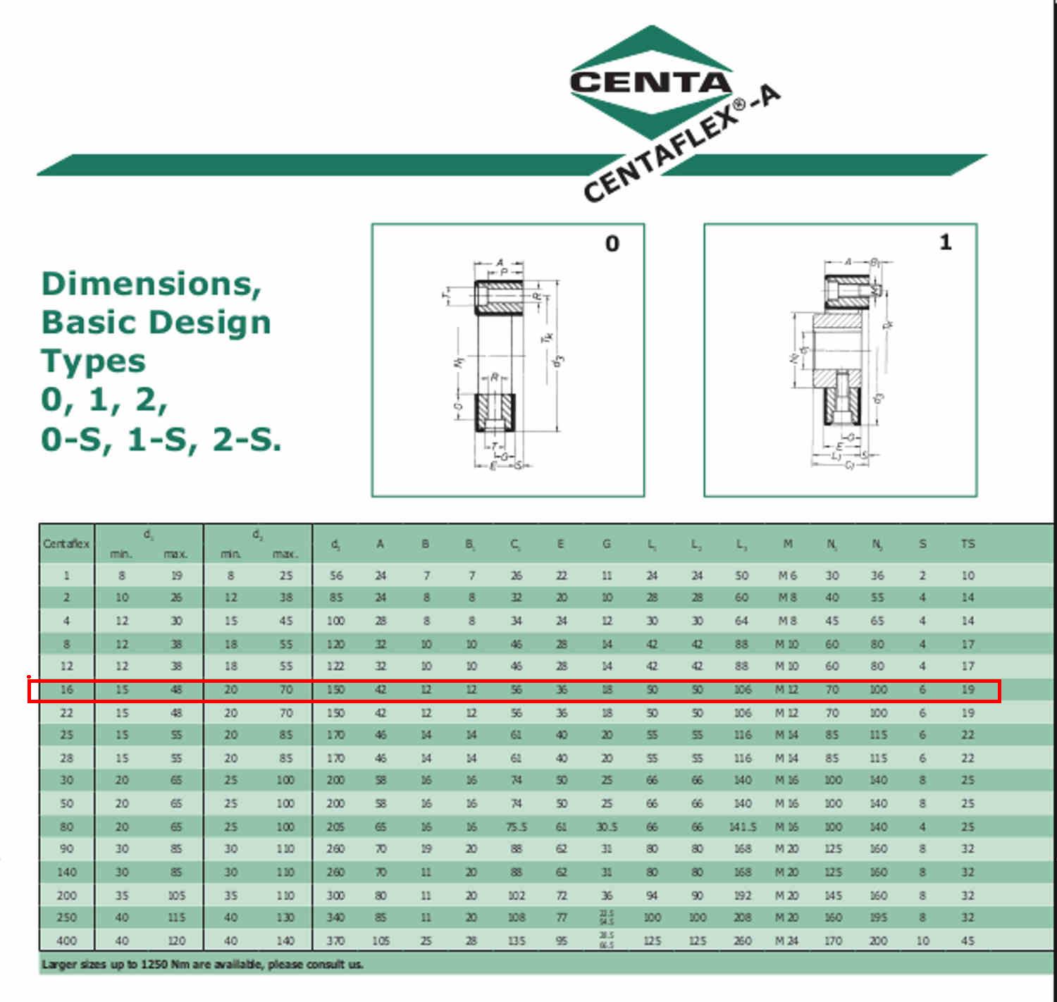
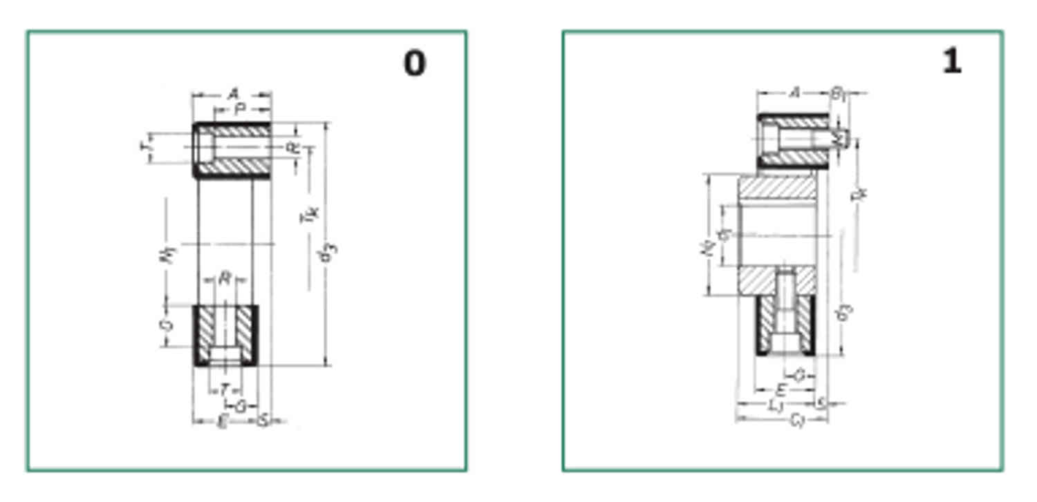
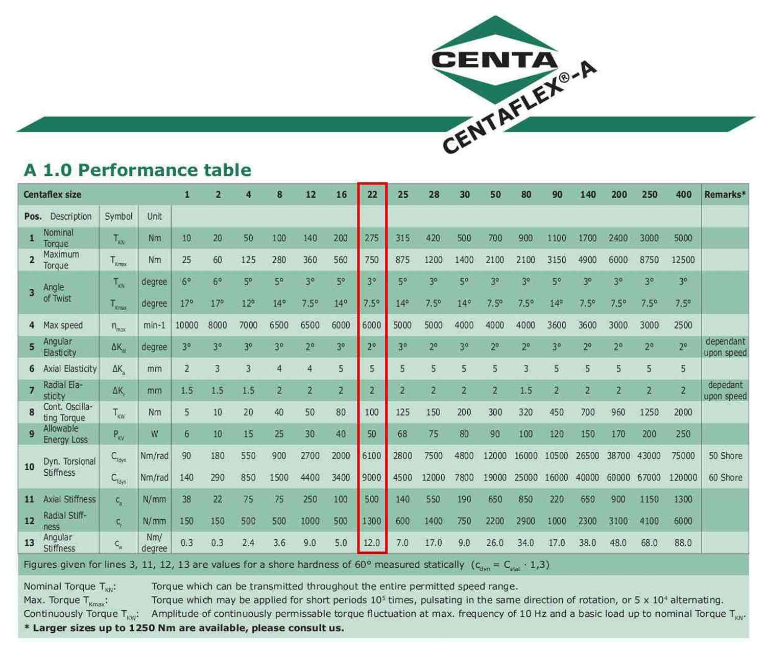
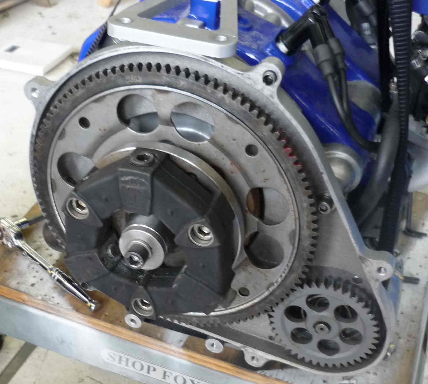
these rubber doughnuts have been used on the rear wheel drive transaxle alfas quite
successfully even under higher HP racing conditionsthey were incorporated (3 of them) into
the shaft between motor and rear transaxle - so were designed to survive at engine
speedThey were needed to counteract any alignment or vibration problems due to the higher
crankshaft speeds compared to an after gearbox shaft.I used to own a 75 alfa 3.0 (Milano
in U.S.) and despite my best efforts, I never had problems with them.They do however
deteriorate over time so need replacing to a schedule if you do not want any
surprises.They will certainly take well over 200 hp and over 7000 revs under severe
conditions, so may work ok under more constant loads
Bruce
Yes I am very familiar with them as I once was a race car designer
for Chaparral Cars. Widely used in rear axles and drive shafts.
They are too stiff with the softest rubber available.
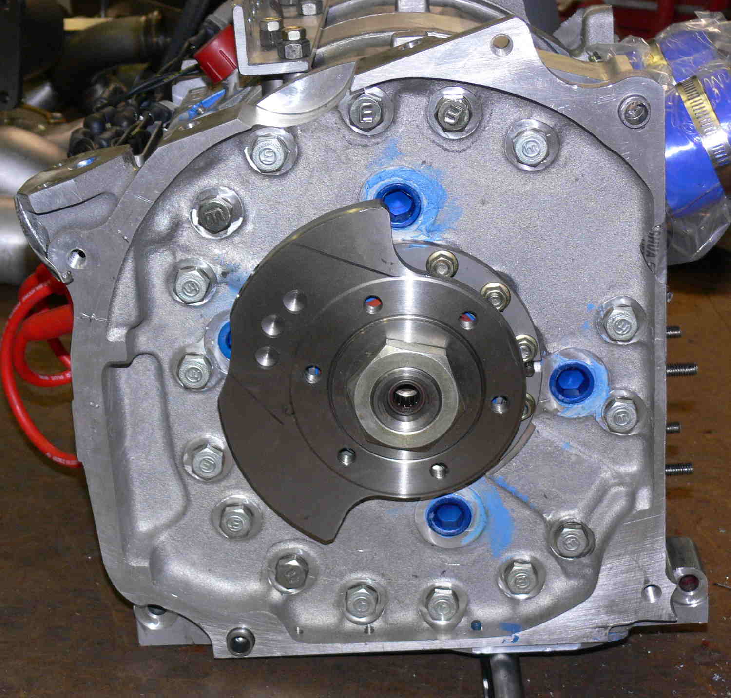
The bolt pattern is wrong for the rear counter weight bolt pattern.
The spline plate has a non standard spline.
Therefore it must bolt to the spline plate and the counter weight.
No room for that.
It must be less than 43 mm or 1.7 inches long including the bolt
heads. It must be less than 6 inches or 152 mm in diameter.
If you think you can make it fit make a scale dwg and upload it.
It must handle 300 foot pounds or 407 Newton Meters average.
Peak torque is twice that.
The RPM is limited for the amount of torque we need.
This part may have caused a crash in the rotary powered
airplane it was used in.
Been there done that.
I am not willing to take that chance again.
However it is a free country :)
Paul Lamar