My experience has been that the weak link isn't necessarily the
planets, but something else, like the rivets holding the flex plate
adapter to the hub, or the weld/pin attaching the sun gear to the
input shaft, etc. I was curious as to the design spec for this box. I
know you're trying to keep it light, but there's a limit to where you
are willing to go.
Mark S.
Has anybody pulled down one of Tracy's psru's that has some time on
it. I'm aware of Dave's sun gear issues I was wondering how the rest
of the unit was holding up. Dave did you install a second pin in the
sun gear, If so have you inspected it since? Just curious as to the
results.
Graeme Riley
It is showing some weakness in the higher 3 rotor HP levels. The flex
plate is cracking.
IMHO it is due to the lack of an effective torsional damper. In
effect capturing the rubber bushing in an enclosed metal box like
Tracy has done is no damper at all.
They don't work as one might think. If you totally enclose a rubber
bushing (as Tracy has done) it no it longer operates as rubber. It
acts as a solid. Rubber is no more compressible than hydraulic
fluid.
Motor cycle style rubber bushings can be made with red RTV in a
Teflon mold. Good to 500 F.
Paul Lamar
The welded version can use the stock 10 mm 1.25 mm pitch bolts as it
is only .075 thick which can replace the stock clamping plate
The walls are rectangular .75" by 1.5" 4130 tubing from Aircraft
Spruce. I have some in stock.
There must be only three walls because there are six 10 mm bolts.
Here is what it looks like. It fits the stock 2 rotor flex plate but
does not stress it. All torque is transmitted by the six 10 MM
bolts.
I will weld one up and send it to you for testing Mark.
Paul Lamar
BTW asymmetric rubber bushing might work out to be the best
configuration. Most of the rubber on the compression side. The acid
test will be the lowest engine RPM that does not cause resonance.
That does not mean it is not mitigating destructive torque pulses at
higher RPM's. The kind that shear bolts and pins.
Paul Lamar
Paul,
That looks good to me. How do you plan on making the silicone
dampers?
If you can get the pieces cut to size and send it all to me, I can
weld it up and then test it.
Mark
I was thinking we could buy fabric reinforced silicone rubber sheet
from McMaster or AC spruce and cut it to shapes. Then glue them
together with red RTV to form crude 3D shapes..
OK I'll do that Mark. I think I have located mild steel tubing of the
right sizes. The tube parts are lightly stressed so you can weld it
to the 4130 parts.
Paul Lamar
Paul,
Something I need to add to the mix. My rear psru seal has worked its
way out of its bore more than once resulting in damage to the seal
and loss of oil. The fix I came up with was to install three
button-head screws into the flywheel side of the psru adapter plate
in order to retain the seal. These screws may interfere with your
"stacked bearings" solution to the flex hub adapter. I just wanted to
mention this as a possible problem area as we proceed with the
design. As far as I know, I'm the only one that's had this problem.
So, I'm keeping my fingers crossed on whether or not the double
stacked bearings are necessary, hopefully not.
Mark
They can stay there. The spline plate can be turned down on a lathe
so the spline plate bottoms out the splines short of the screws and
clears the screw heads.
As it is now the seal surface on the input shaft extends back beyond
the lip of the seal to the splines which start some where on the back
side of the adapter plate.
The rubber coupling expansion will tend to reduce the force on the
helical gear thrust bearings.
Paul Lamar
Mark, Next time you have the gear box off please measure the distance
from the lip of the seal to the start of the splines.
Also send some pictures of your helical gear thrust bearings.
We might be able to adjust the spacer to get a few more thousands
seal lip clearance before the start of the splines.
This is what it looks like on the RV4 with the old 2.17:1 gear box.
The splines go into the seal somewhat.
Paul Lamar
In the future when one is trying to be helpful think of the space and
weight of what one is suggesting. Get a dwg. of the device and see if
it will fit in a 6 inch dia. cyl. and 1.7 inches long. The devil is
always in the details.
Paul Lamar
Paul, I have been following this thread and have a couple of
questions for you. You point out that rubber does not act the way we
want when constrained. IIRC your damper design uses three rectangular
tubes per side in such a way as they mesh between each other. This
leaves six spaces for rubber dampners. So effectively your rubbers
are constrained by those six tubes and the plates. If the rubbers fit
too tight and you have no dampening, too lose and you have too much
backlash. How do you size and fit the rubbers ? Can you, do you vary
the elasticity of the blocks ? Can you, do you adjust the shape of
the blocks to find a happy balance between dampening and backlash ?
Or do I have the design all buggered up in my head ?
John Gibbons
The rubbers are not necessarily perfect triangles. They can be any
shape. Feel free to experiment.
Mark S will probably come up with suggestions.
BTW a fabric reinforced silicon rubber cutting tool can be made from
parts of a box cutter blade bolted to a block of aluminum. Stick the
box cutter blade in a vise and break it off to desired lenth. Use an
arbor press or drill press to cut the parts.
Paul Lamar
I had a lot of trouble cutting these rings. I bought a cheap Chinese
14 chop saw from harbor freight and spent a whole day modifying it to
cut six inches. I was not happy with the results.
Then I found a guy with a nice collection of old machine tools.
Wonder of wonder he had a rare lathe with a 9 inch hole in the
spindle. Piece of cake:) The secret to big stuff is a big tool:)
I shipped the prototype to Mark for ground testing on his 300 HP
P-port 3 rotor. The PO says he will get it on Saturday.
Paul Lamar
Hi Paul, The SGF couplings are cord reinforced, not just rubber
in
compression like the Centaflex and are thus more compact and have a
higher speed raiting. If I am reading their chart correctly the -025
is rated at
420Nm. is 120mm OD and 18mm thick. Calculated burst speed is over
14,000
rpm. I think I have seen that they can be mounted with pins on one
side for assembly, maybe on both sides. That would get rid of bolt
heads. Three pins in, three out. Three 10mm diameter pins in
single shear? It might work.
Murry I. Rozansky
Where is the drawing and the pdf catalog ?
Since it is fabric reinforced it is stiffer than the centflex.
I tried the softest centiflex they and it was still too stiff.
Your missing a point. We have total control over the stiffness as we are making
our own rubber bushing.
We are done designing the coupling.
We are moving on to bigger and better things :)
Paul Lamar
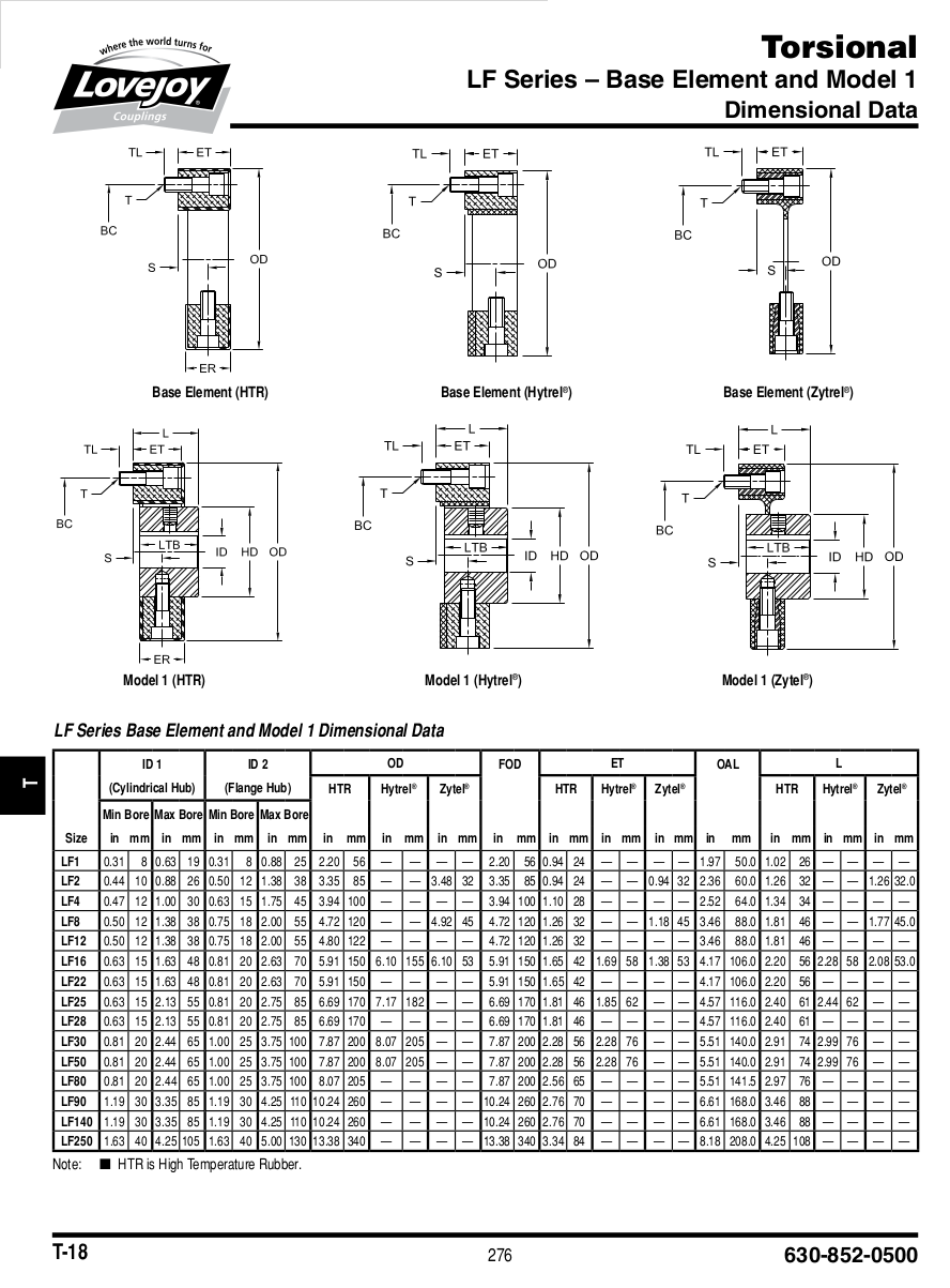
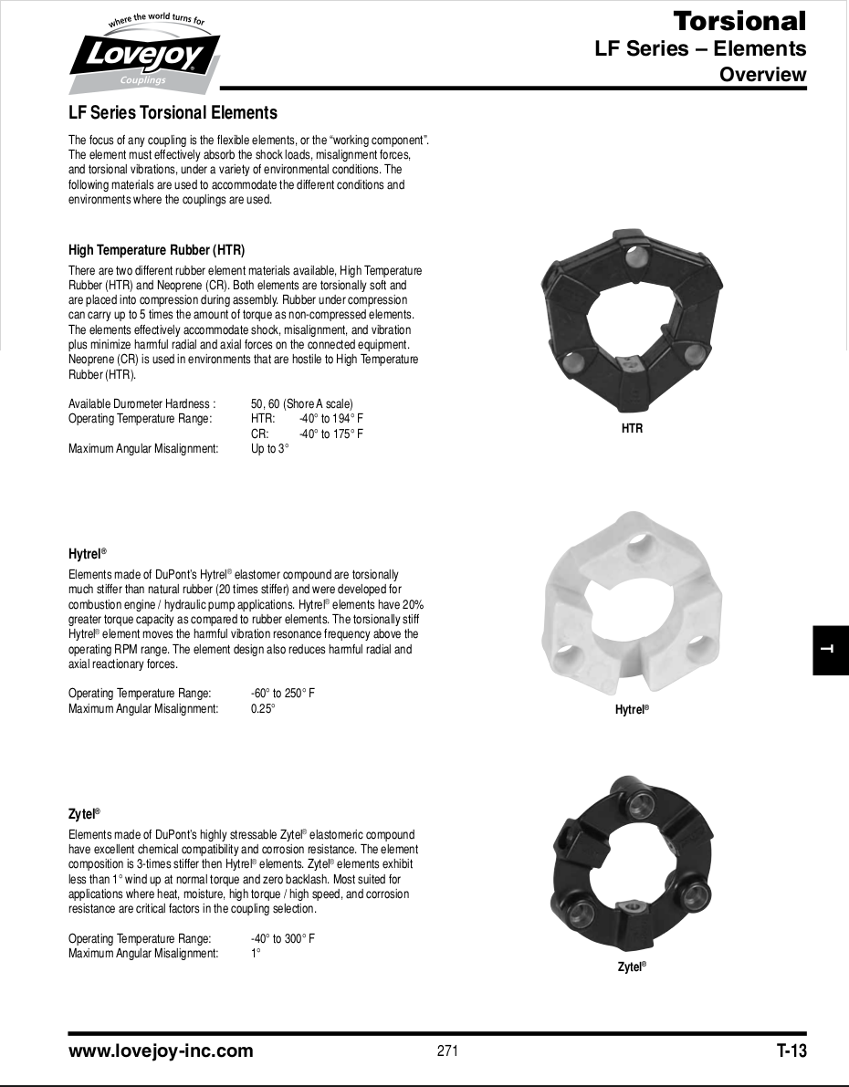
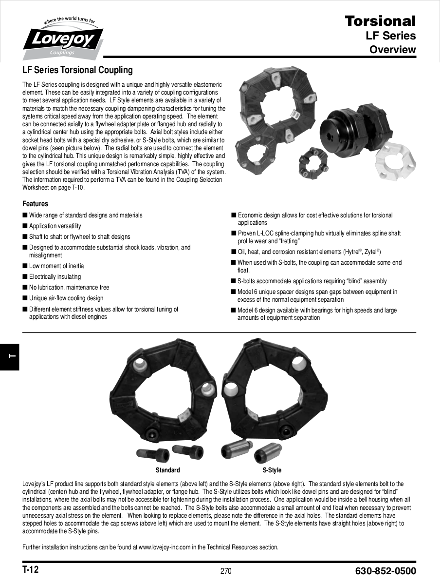
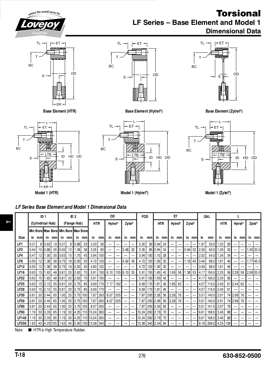
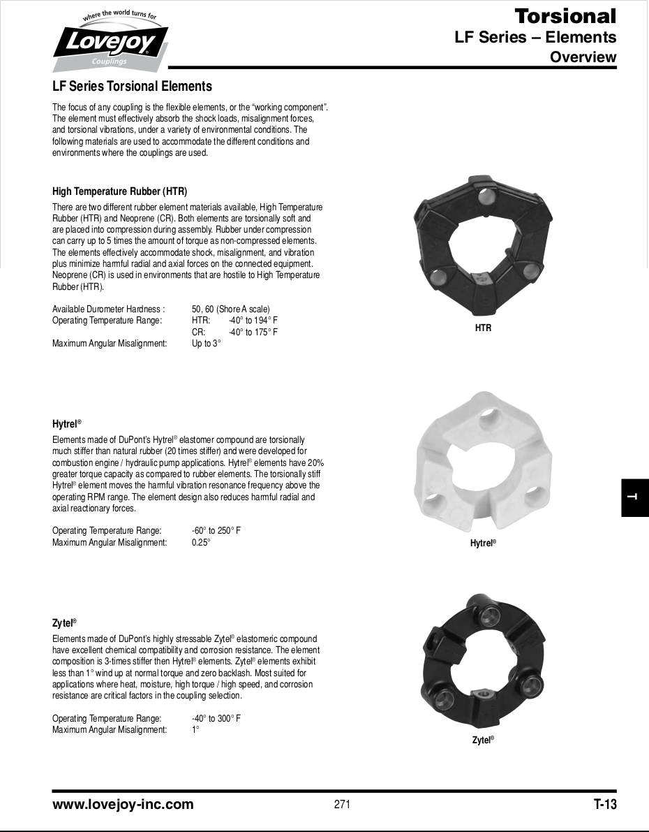
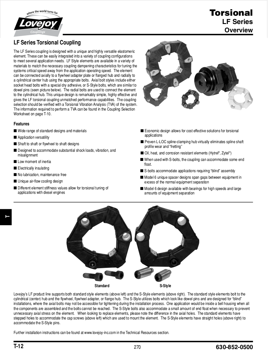
Might I suggest taking a look @ love joy coupling.com
Ben Lane
Which version did you have in mind?
Paul Lamar
Thought it might give food for thought, no specific model.
Ben Lane
The only one they have with a snow balls chance of fitting
is near identical to the Centflex. Too stiff and no way
of adjusting it.
Paul Lamar