Hey Paul,
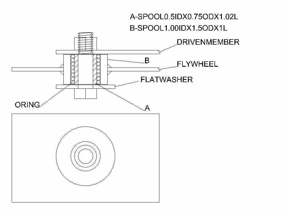
Here's a concept that you might try to absorb the torsional vibration in
the drive line. The basic idea can be adapted to suit whatever
configuration you need by varying the lengths and diameters of the spool
pieces and the thickness of the O rings used.
Thicker O rings will make the assembly more compliant as there is more
space available for the O ring to compress under load.
I've used these to mount compressors and engines. They are quite
durable and effective at isolating vibration.
Use as many as you need to carry the torque from the fly wheel to the
driven plate.
If you make the inner spool 0.5" longer you can add a 1/4" thick
corrugated rubber pad on each side of a thicker foundation plate,
instead of the thin flywheel plate, to provide vibration absorption
along the spool axis.
This design is very flexible and can be adapted to many uses.
I hope you can open the dxf file.
Mark LaPierre
Thanks Mark but any suggestion must be low cost and fit in
the confines of Tracy's basic design. A new flywheel or flex
plate is not in that category. The standard 13B auto tranny flex plate
is not strong enough to be modified to incorporate this design.
We have discussed that extensively on here.
It is expensive to make a new flywheel or flex plate
simply because of the ring gear problem. That is the gist of
the problem with Tracy's existing design.
We therefore have removed any reliance on the flex plate
to transmit the torque. It's only function now is to start
the engine.
Also I might add angular deflection is limited by the size of
the O-rings implying low damping. One needs a lot of rubber
volume to deal with the heat of vibration damping and shock absorption.
The gear box is impacted by two shocks per revolution of the
two rotor 13B.
Visualize a large spinning flywheel (prop) being kept spinning by
repeatedly hitting it with a hammer.
That is what all intermittent combustion aero engines do.
It is really bad if the part being impacting with the hammer
is connected to the fly wheel with a gear train.
A fluid coupling would be ideal but they are large, heavy and complicated
and there fore expensive. I just bought one as part of the
turbo compound gear box.
A centrifugal clutch should work simply because it would
be designed to engage above the resonate system frequency.
Above that RPM that it would do nothing to mitigate the shock on the
gears.
An overrunning clutch (one way) has the same problem, No softening
the blow on the gears. One would now have two devices subject to
impact in series.
Our goal is to soften the rubber and lower the resonant frequency
to a reasonably idle RPM and mitigate the shock on the gears and have
the gear box live a long and useful life. All at low cost and fitting
inside the confines of what we have.
Paul Lamar