I will use a small tack weld across two splines, two or three places. The
welds will need to be flush so the input shaft will pass through the seal.
That should be plenty to keep the spline plate assy from rubbing against
the seal.
BTW, I double-checked and my spline plate is attached with a dozen, or so,
AN3 bolts. I previously stated incorrectly they were AN4.
Mark
On Sat, Jun 22, 2013 at 6:39 PM, rotaryeng <
rotaryeng@earthlink.netwrote:
Paul,
The box of parts arrived today. My first question is regarding the 6
blocks. There are 3 short ones, and 3 longer ones. So, which half
of the damper do the short and long blocks belong?
As I recall, you plan to keep the splined hub from moving forward
(away from the flexplate) by brazing the psru input shaft so as to
limit the travel of the splined hub, correct? What about the temper
of the shaft? I'm not very comfortable with heating the input shaft.
Maybe 3 or 4 spot welds with the tig welder, bridging two splines
each and allowing it to cool back down between each tack weld.
Mark
The short ones go with the front disk that bolts to the spline plate.
Necessary to clear the 10 mm counter weight bolts.
Yes brazing might be too much heat.
It does not take much to limit spline travel. Staking it with a hammer
and center punch might
work.
Paul Lamar
Paul,
I just tried a fit check on the dish-shaped part that bolts to the
counter-weight. When held up to the 13b flex plate there is a .030" +/-
gap between the mating surfaces of the adapter and flex plate. The
interference is around the perimeter of the dish-shaped part. If bolted up
as is it would likely cause warping of the welded assembly.
When held up to a 20b flex plate, there is a smaller gap which appears to
be caused by the tack welds. If welded from the inside it should work.
So, I will weld it from the inside and then grind down the spot welds, and
use the 20b flex plate instead of the 13b plate. That looks like it should
correct the problem. I believe the 20b flex plate is the same as the
Renesis flex plate, so others could do the same, or you could reduce the
diameter by about 1/4".
Mark
Yes I noticed that. Stick a washer in there. I just got
my new $99 six inch chuck installed with reversible jaws. Took me all
damn day. I had to make a precise adapter. Ever try to adapt
a chuck with only one lathe? :) The lathe you are making the
adapter for :)
Send me your spline plate and I can cut the offending
portion off :) Or we can enlarge the hole in the front
coupling to pilot on that. Probably a better idea.
In the mean time for testing use some washers.
Also if it is too long some material on the front
side can be removed.
Paul Lamar
Paul,
I think you misunderstood what I was trying to describe. It is the large
bowl-shaped part that bolts to the counterweight with 6 - 10mm bolts that
is the problem. It does not sit flat against the flex plate as it should.
I could use the doubler ring that is normally used with the flex plate to
take up the gap, but that would move everything toward the psru by .030",
or so. That may not be a problem. Or I could use the 20b/Renesis flex
plate. That would allow the bowl-shaped piece to sit flat against the flex
plate and there will be no change in the spacing. Since I have a spare 20b
flex plate, that is what I will do.
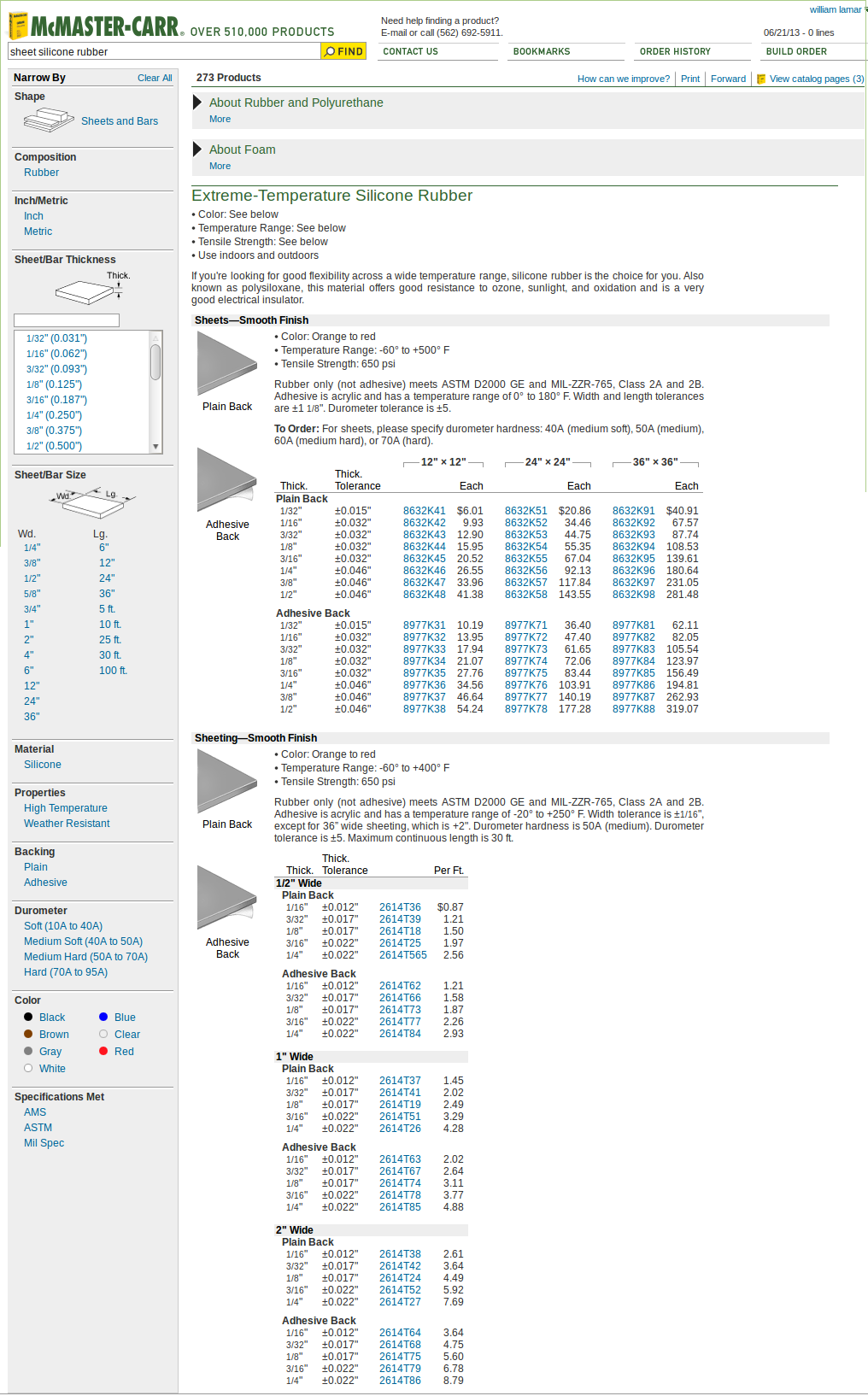
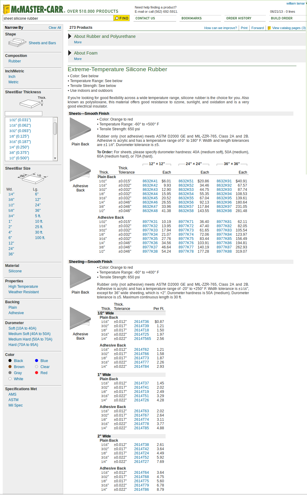
I will need to order some reinforced silicone material from McMaster. Any
suggestions on type and thickness?
Mark
I understood. Weld it on the inside and send it to me and
I will round off the outer corner in the lathe. That will maintain
the pilot on the counter weight. Don't space it out as it may not
run true.
Any of this will work.
Paul Lamar