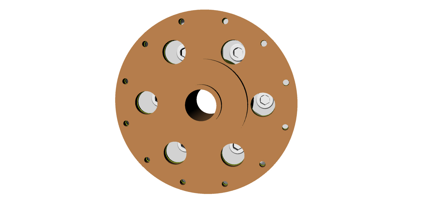
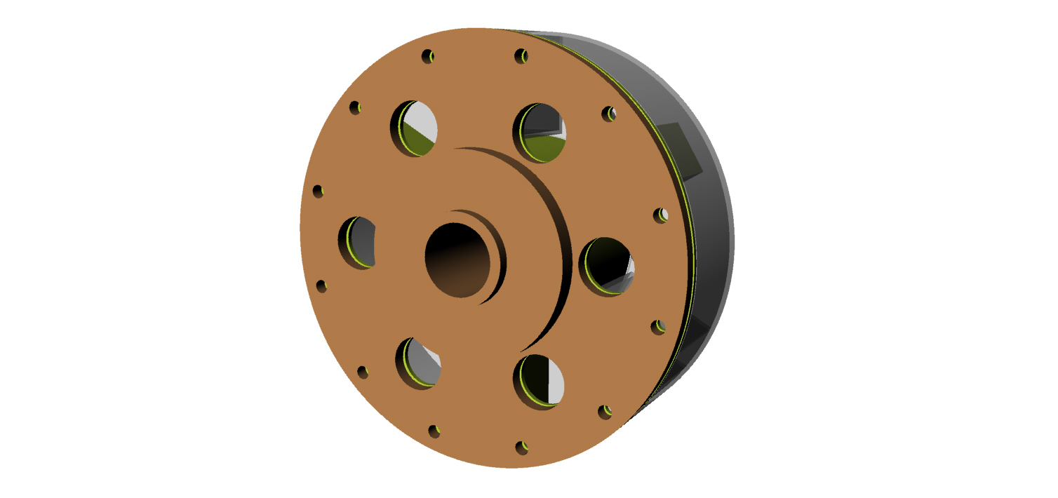
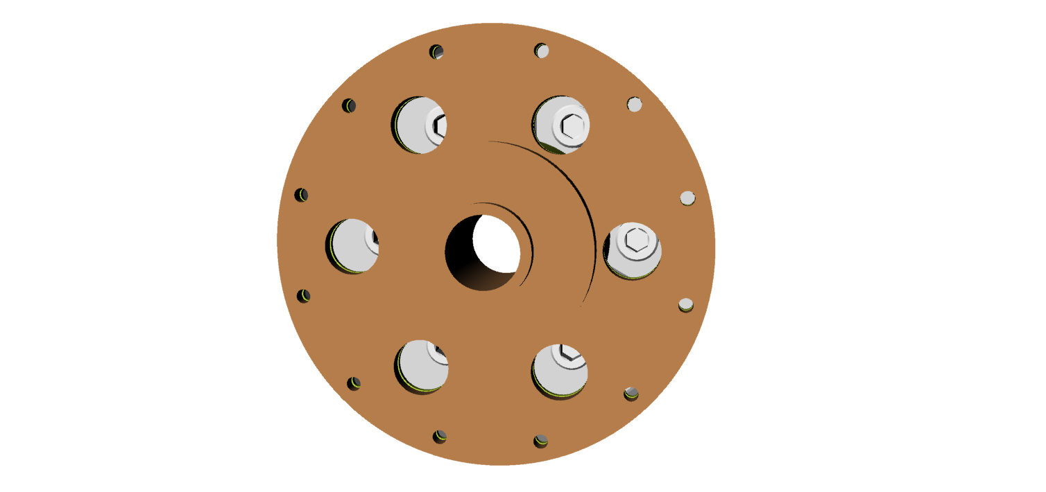
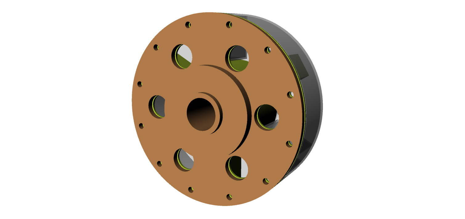
Here is what it looks like with a 3 inch inner tube and socket
head metric 10 mm bolts. I think this is an improvement but
we can still test what we have. This is a minor change in the
over all scheme of things.
Paul Lamar
That works too. My thought was to extend the three "paddles". By
extending the paddles, there is more space for the silicone.
FWIW - From looking at the welded up assy, I don't see how this little
assy will be able to absorb 350 hp.
Mark
Two ways to get HP. Torque or RPM.
The rotary is RPM. Lets say it generates 350 HP at 7500 RPM.
What is the torque?
HP = T X RPM /5252
350 = T X RPM / 5252
350 X 5252 / 7500 = T = 245 foot pounds.
3000 inch pounds. Divided by 5 inch diameter = 600 pounds total force.
3 rubber lumps 200 pounds per rubber lump.
One inch high by 1.4 inches is 1.4 square inch.
142 psi.
It is hard to quantize rubber for compressive strength
because it expands in other directions 90 degrees to the load.
The tear strength is 580 pounds per square in or about 4 MegPas.
Cut 4 pieces 1 inch by 1 inch. One square inch. Stack them up on the
floor. 3/8th of an inch thick roughly. Best to glue them together
with red RTV and let it cure for 24 hours.
Put the heal of your shoe on the rubber stack and balance with on foot.
See if it springs back to shape.
Paul Lamar
Hey Paul,
I think I see an error in your calculations.
245 foot pounds = 2940 inch pounds
2940 inch pounds divided by 2.5 inch radius = 1176 pounds force
1176 pounds force divided among 3 rubber lumps = 392 pounds force per
rubber lump.
How much clearance is required through the center of the torque damper?
Your pictures scale to about 1" ID clear hole. Is that correct?
Mark LaPierre
Yes. You are right. There are only three compressions chambers.
There are also three tension chambers. If we use liquid
and it bonds in the tension chambers the stress on the compression
chamber is half that. The max tensile stress for curred silicone rubber
is 580 psi. BTW this is the same stuff they use to bond glass plates
together to make fish aquariums. It is very strong as a glue
in tension.
The latest version gives a void of 2.75 inches in diameter.
That is with a inner steel tube cylinder of 3 inches OD.
Some of that is taken up with the 2" dia. spline plate and some is taken
up by the roughly 1 inch diameter gear box input shaft that pilots in
the eccentric shaft. Just like a manual transmission.
Paul Lamar
Paul,
Maybe I misunderstood your last post, but if you're suggesting using a
pour-able silicone to provide 3 "tension chambers" as well as compression
chambers, then I don't see how we could assemble this device onto the
engine with everything bonded together. Its got to be so that we can bolt
the first section to the engine, add the silicone and spacers, then slip
the splined hub assy onto the first half. What am I missing?
Mark
With the coupling off the engine and 1-1/2" long
silicone hose with 5/8" ID over the 10 MM socket head screws and six 5/8
holes drilled in gear box side plate and spline
plate opposite the 10 mm bolts it could be done.
You then use a long Allen wrench to bolt the coupling to the counter
weight after the silicone is curred.
That is a down the road option. Run the way it is. we need to get
a feel for the resonant frequency first and for most.
Paul Lamar