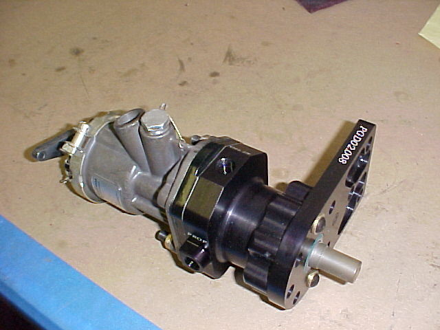
I am still wondering why you are re-inventing the wheel with the CS
governor. Many of you are not using the CAS and going with a hall effect
sensor. The engine already has the provisions to turn the CAS at half the
engine speed. It shouldn't be too difficult to use the spline adapter of a
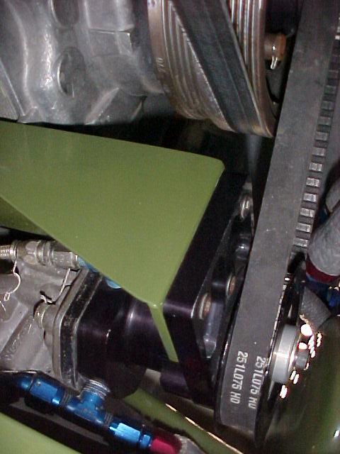
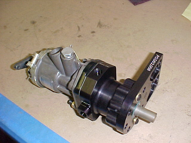
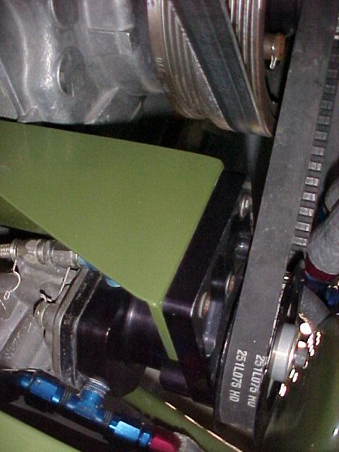
Lyc or Cont machined in a block of aluminum bolted to the front cover. Oil
can be picked up from the line out of the front cover and routed to the
gov. The output line from the gov can be run to the PSRU.
The only necessary mods to the psru would be make a hole in the shaft where
the bushing is so that the pressurized oil can get to the hollow shaft.
Knock out the little freeze plug in the end at the prop and now the oil can
get to the prop.
If we run the engine at 8000 rpm, and the gov runs at half engine speed,
that means the gov is running at 4000 rpm. In a the geared continentals in
the Tbone at our airfield, the engines run out at 3900, with the govs
bolted to the engine and running at engine speed.
And, there are a few electrically actuated cs props out there as well. My
McCauley CS prop weighs around 45 lbs, more than twice what Catto said a
carbon fiber would weigh.
We are making new parts to take care of the resonating problems, but we
seem to be determined to stick a heavy prop on there that will make the
resonance problem worse.
Anyway, as far as an oil fed CS unit, it doesn't seem that difficult,
really. Myself, I will most likely go with the CATTO or an electrically
actuated CS prop.
Kevin Alderman
I agree with most of what you are saying but the oil pressure boost
pump in the gov takes a bit torque. The Mazda CAS drive does not.
"Consider the fact that a standard, single-acting governor such as found on most light
singles and twins (Woodward 210xxx series, Hartzell and MT prop governors) requires less
than 3/8 HP to drive at 220 PSI output pressure. That is 12 pounds-inches of torque at
2000 governor RPM and less than 9 pounds-inches of torque at 2700 governor RPM. If the
pitch diameter of the driven gear in the governor drive mechanism is 1.25", for example,
then 12 pounds-inches of torque generates 19.2 pounds of contact force at the gear faces.
That’s not a very big load, but it can destroy a badly-designed set of crossed helicals in
just a few hours."
The gov should run at prop speed. I think the main attraction
for the traditional metal CS prop is one of cost. An electric composite
CS runs $10K or more.
Paul Lamar
=============================================================
http://www.thaitechnics.com/propeller/prop_control.html
Constant Speed : If an engine driven governor is used, the propeller will operate as a
constant speed. The propeller and engine speed will be maintained constant at any r.p.m.
setting within the operating range of the propeller.
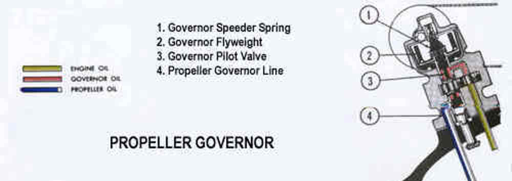
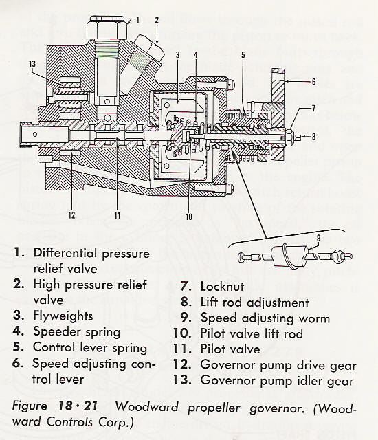
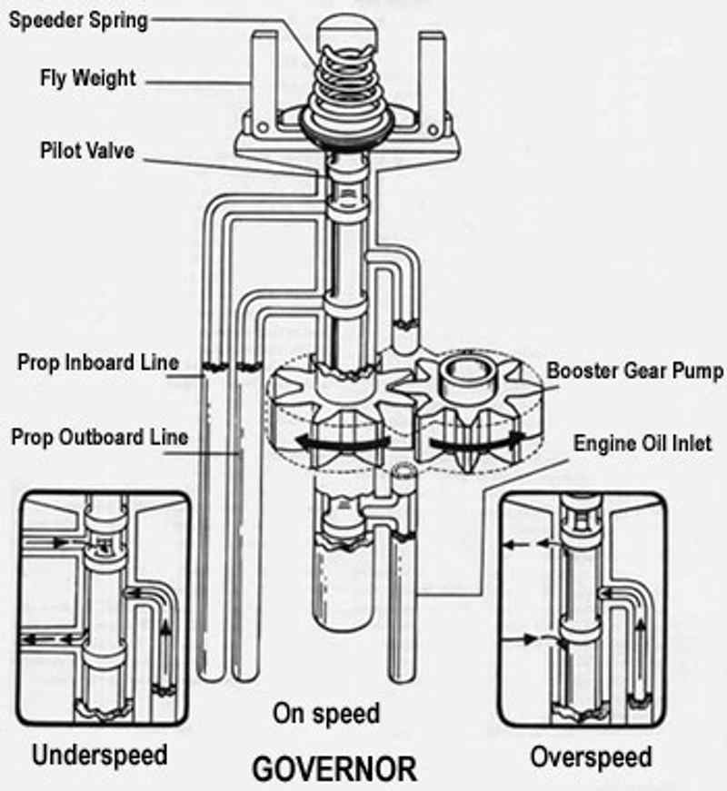
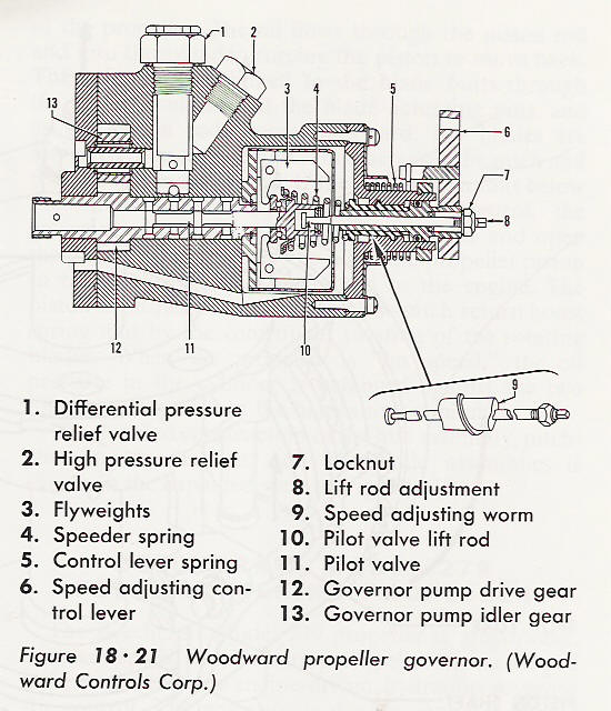
Governor Operation (Constant speed with counterweight ) the Governor supplies and controls
the flow of oil to and from the propeller. The engine driven governor receives oil from
the engine lubricating system and boost its pressure to that required to operate the
pitch-changing mechanism. It consists essentially of :
1. A gear pump to increase the pressure of the engine oil to the pressure required for
propeller operation.
2. A relief valve system which regulates the operating pressure in the governor.
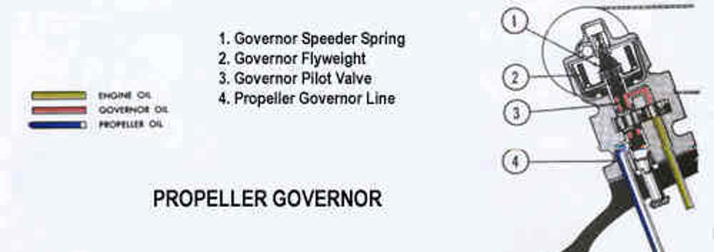
3. A pilot valve actuated by flyweights which control the flow of oil through the governor
4. The speeder spring provides a mean by which the initial load on the pilot valve can be
changed through the rack and pulley arrangement which controlled by pilot.
The governor maintains the required balance between all three control forces by metering
to, or drain from, the inboard side of the propeller piston to maintain the propeller
blade angle for constant speed operation.
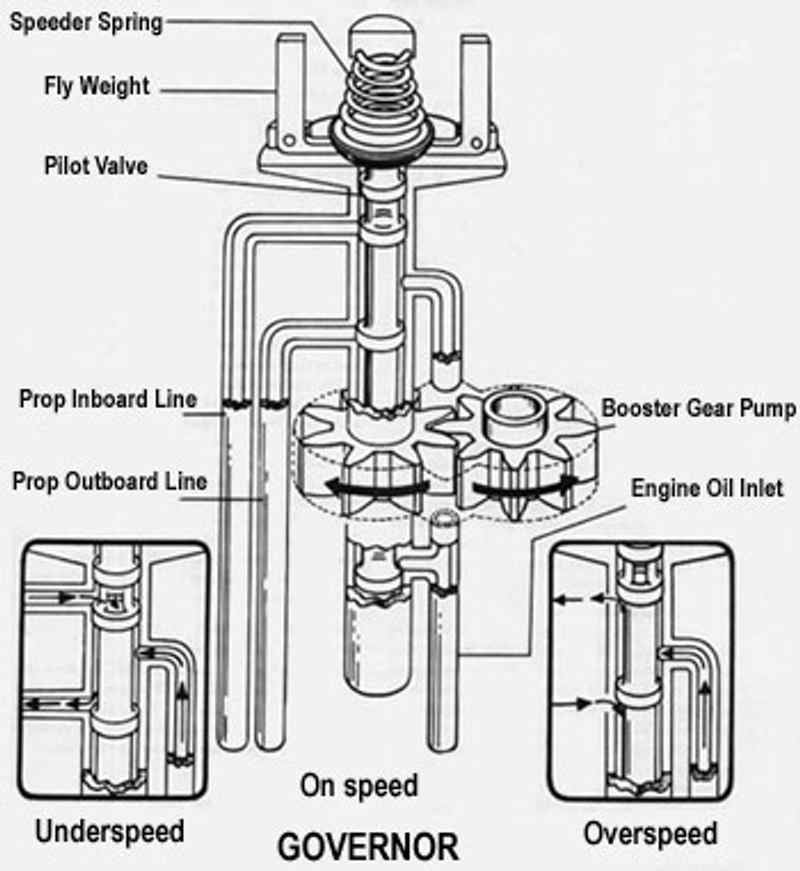
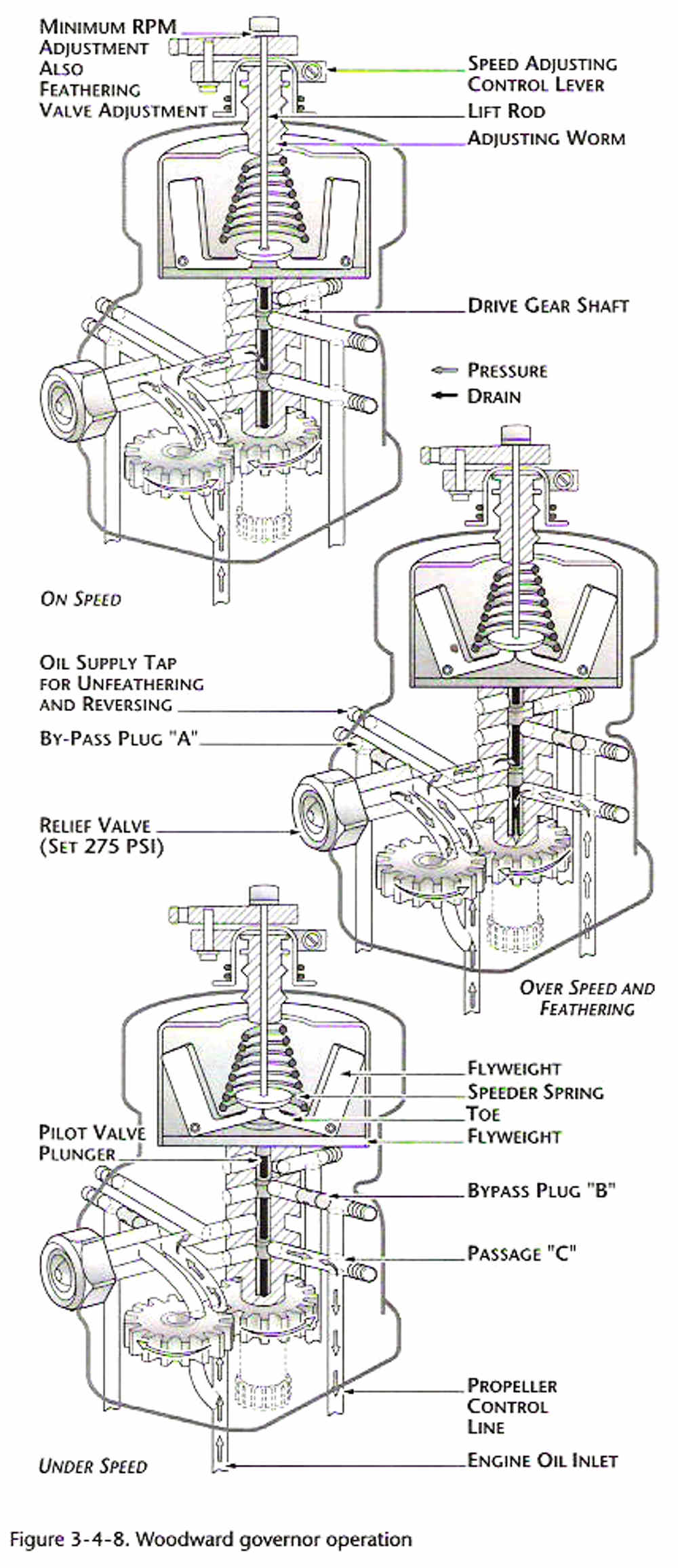
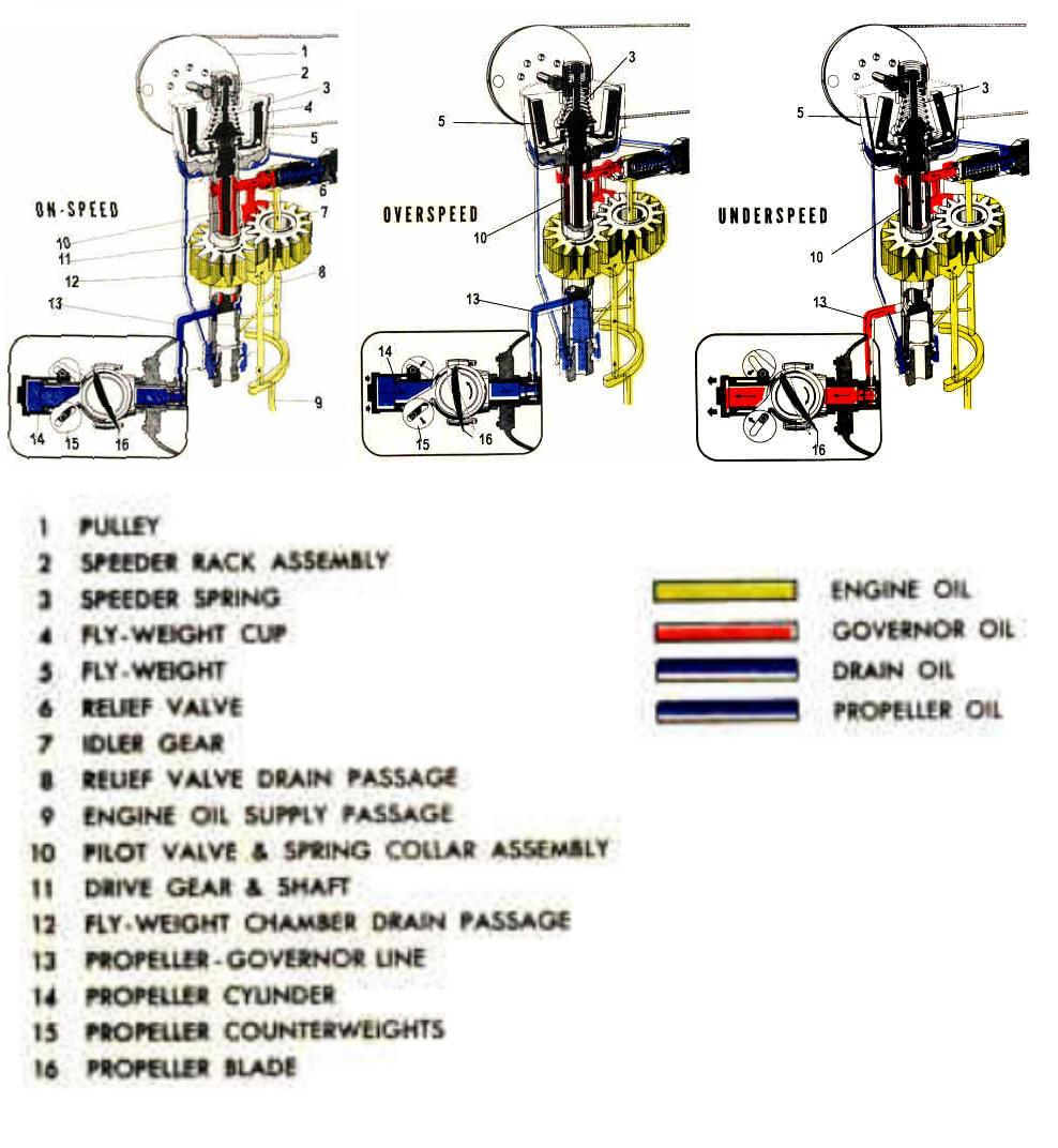
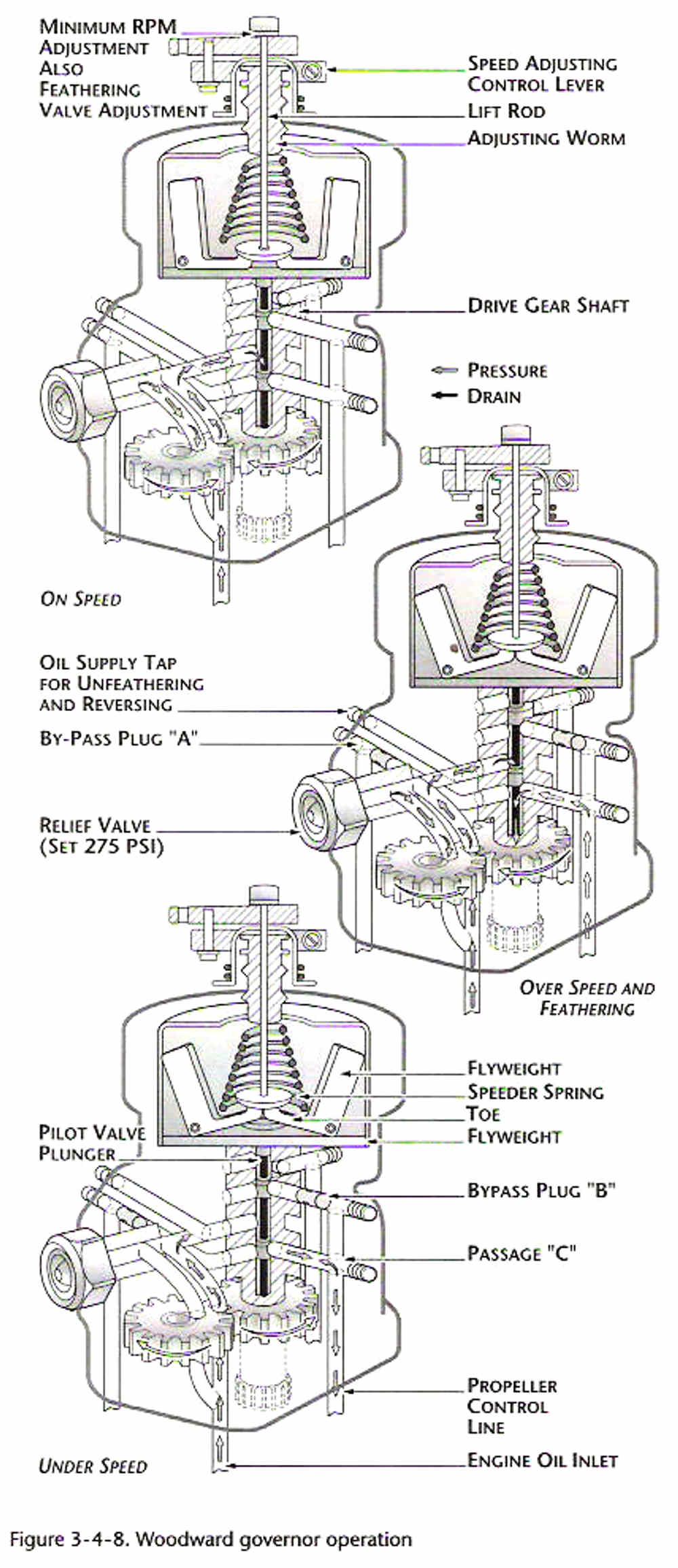
The governor operates by means of flyweights which control the position of a pilot valve.
When the propeller r.p.m. is below that for which the governor is set through the speeder
spring by pilot , the governor flyweight move inward due to less centrifugal force act on
flyweight than compression of speeder spring. If the propeller r.p.m. is higher than
setting , the flyweight will move outward due to flyweight has more centrifugal force than
compression of speeder spring . During the flyweight moving inward or outward , the pilot
valve will move and directs engine oil pressure to the propeller cylinder through the
engine propeller shaft.
Principles of Operation (Constant Speed with Counterweight Propellers)
The changes in the blades angle of a typical constant speed with counterweight propellers
are accomplished by the action of two forces, one is hydraulic and the other is mechanical.
1. The cylinder is moved by oil flowing into it and opposed by centrifugal force of
counterweight. This action moves the counterweight and the blades to rotate toward the low
angle positon.
2. When the oil allowed to drain from the cylinder , the centrifugal force of
counterweights take effect and the blades are turned toward the high angle position.
3. The constant speed control of the propeller is an engine driven governor of the
flyweight type.
Governor Operation Condition
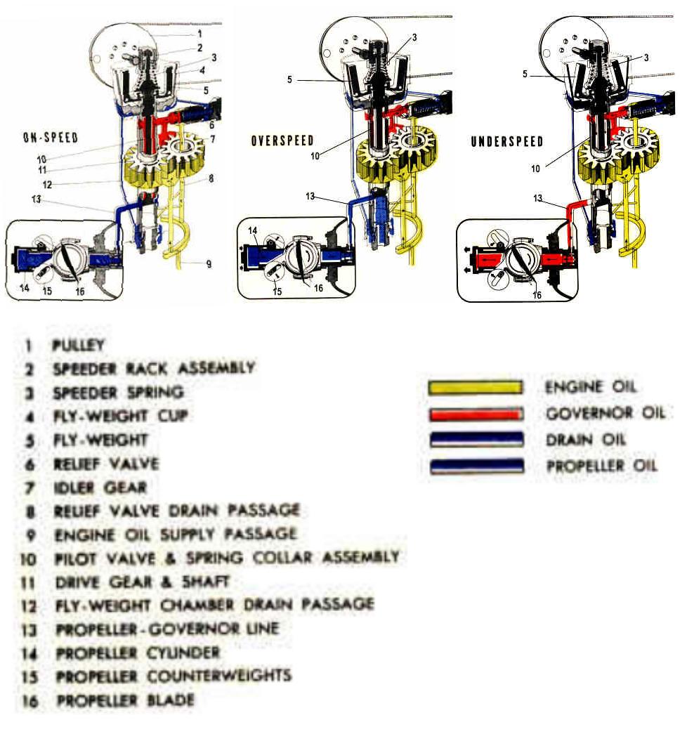
On-Speed Condition
The on-speed condition exists when the propeller operation speed are constant . In this
condition, the force of the flyweight (5) at the governor just balances the speeder spring
(3) force on the pilot valve (10) and shutoff completely the line (13) connecting to the
propeller , thus preventing the flow of oil to or from the propeller.
========================================================