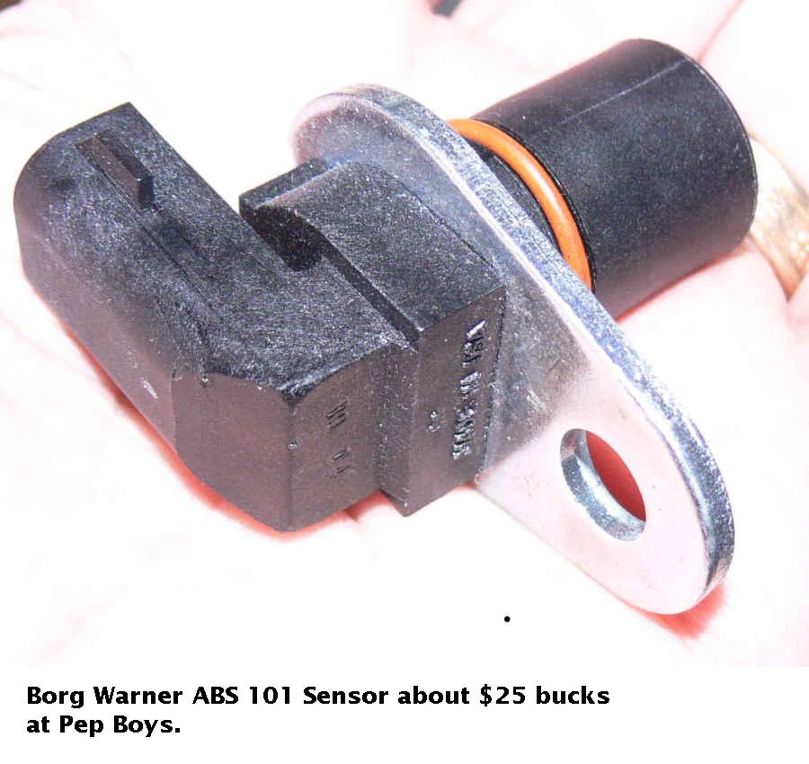
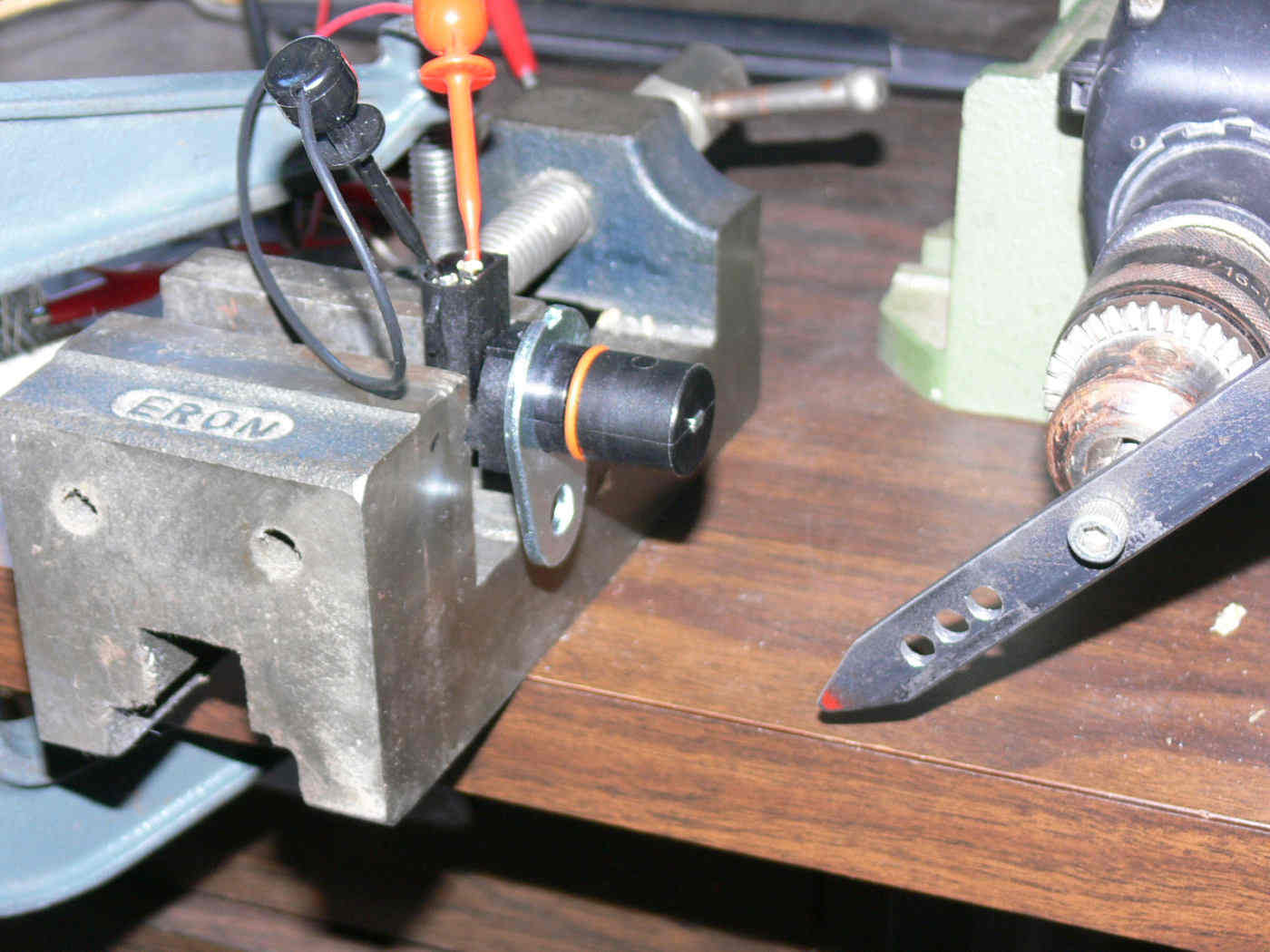
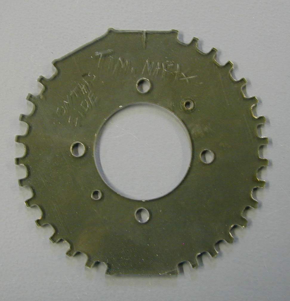
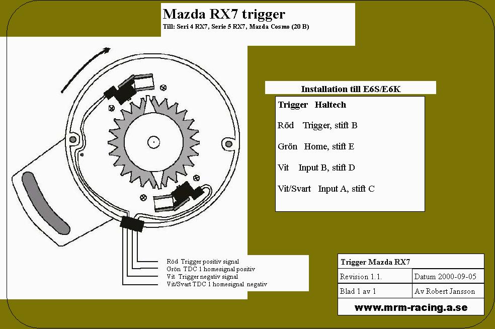
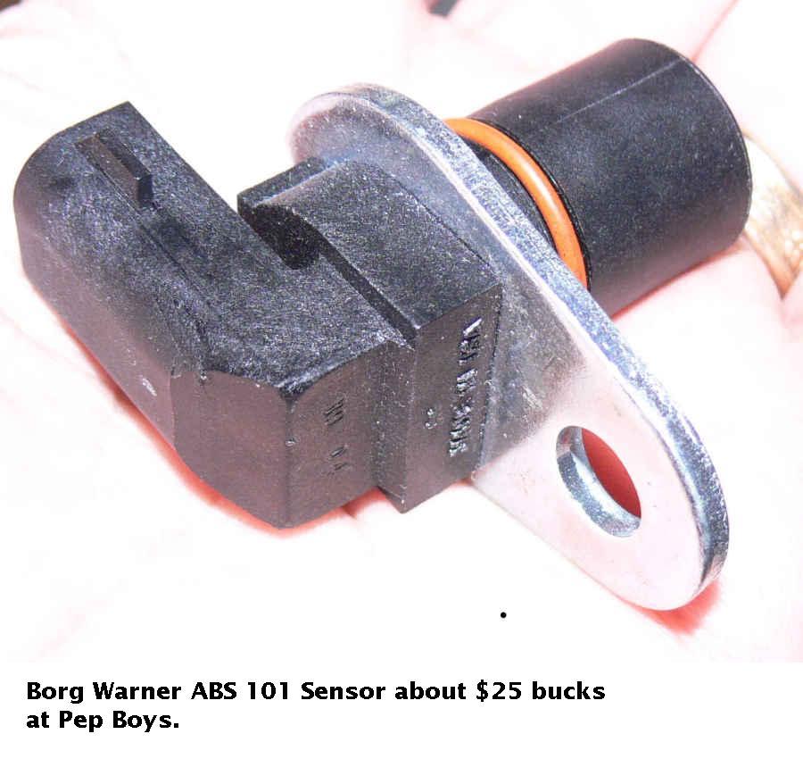
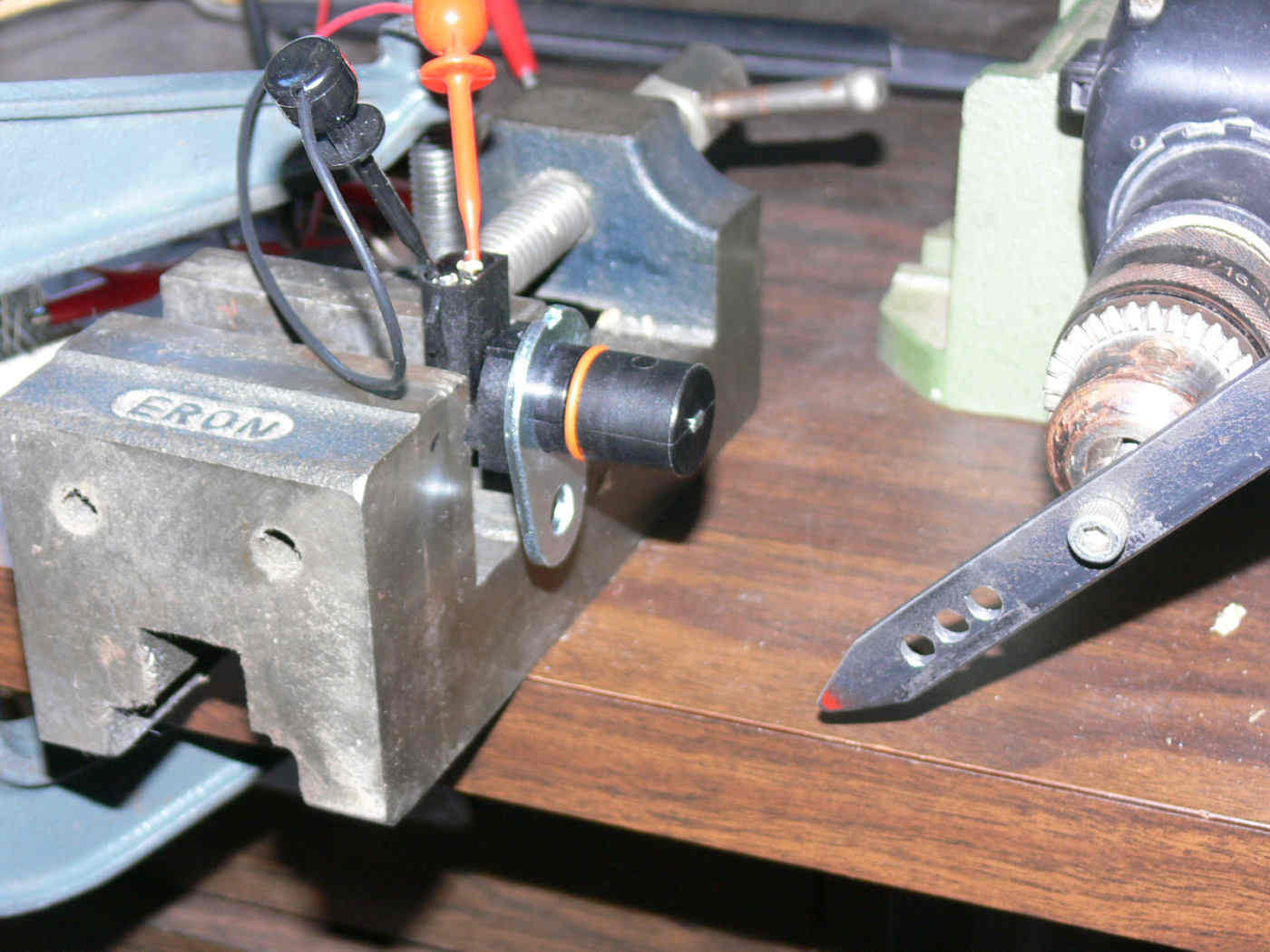
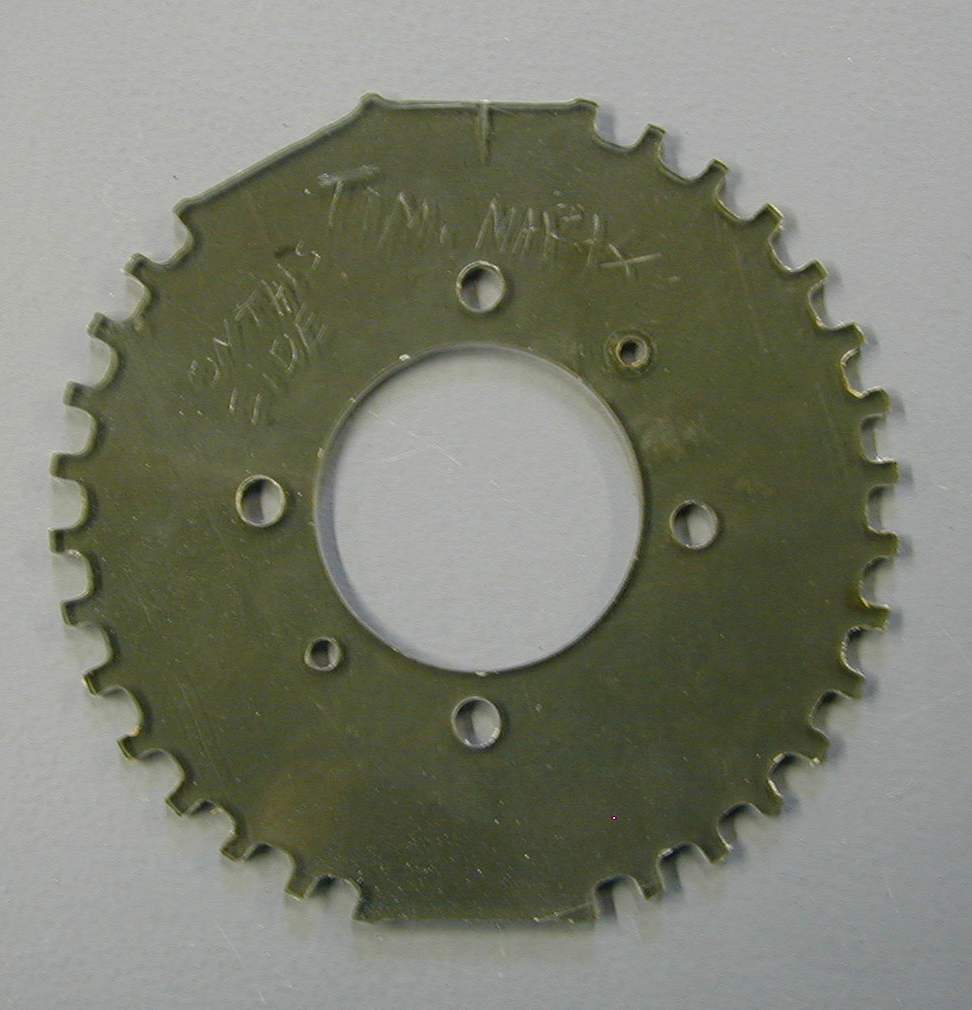
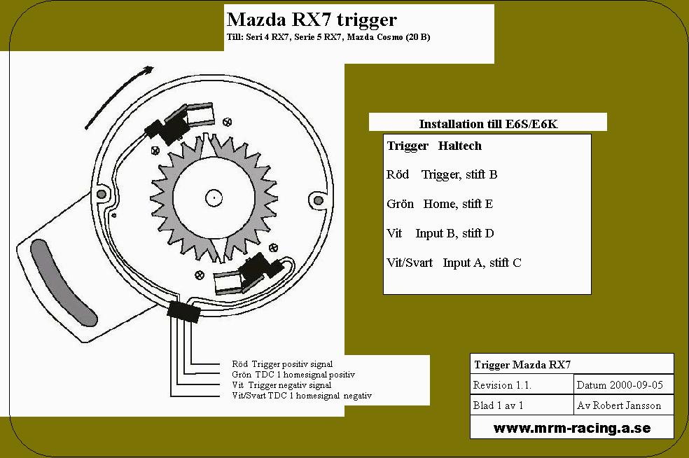
The 3 rotor uses the old 2nd gen Crank
Angle Sensor running at half engine speed.
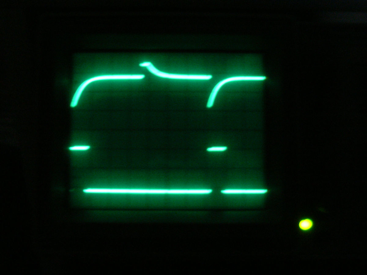
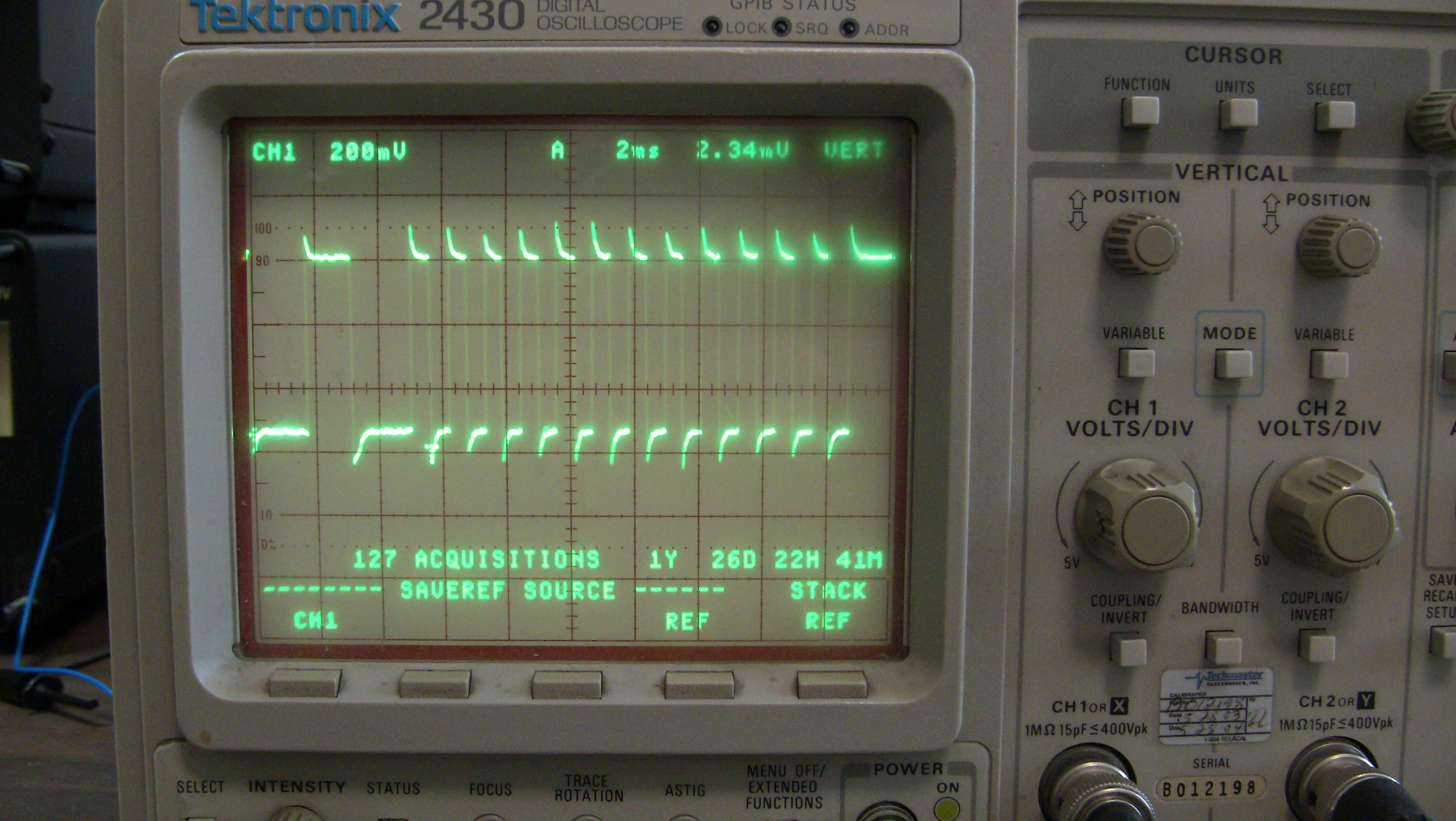
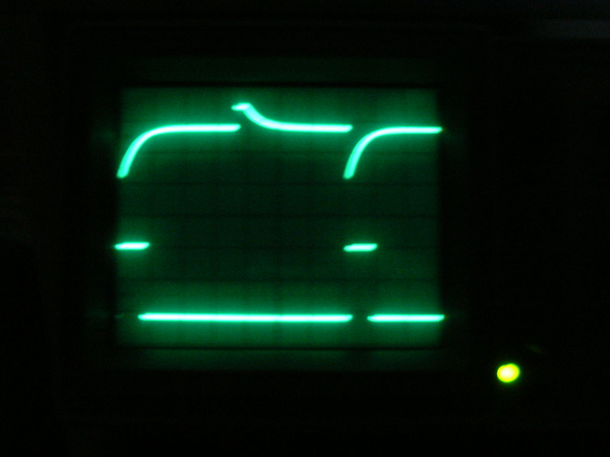
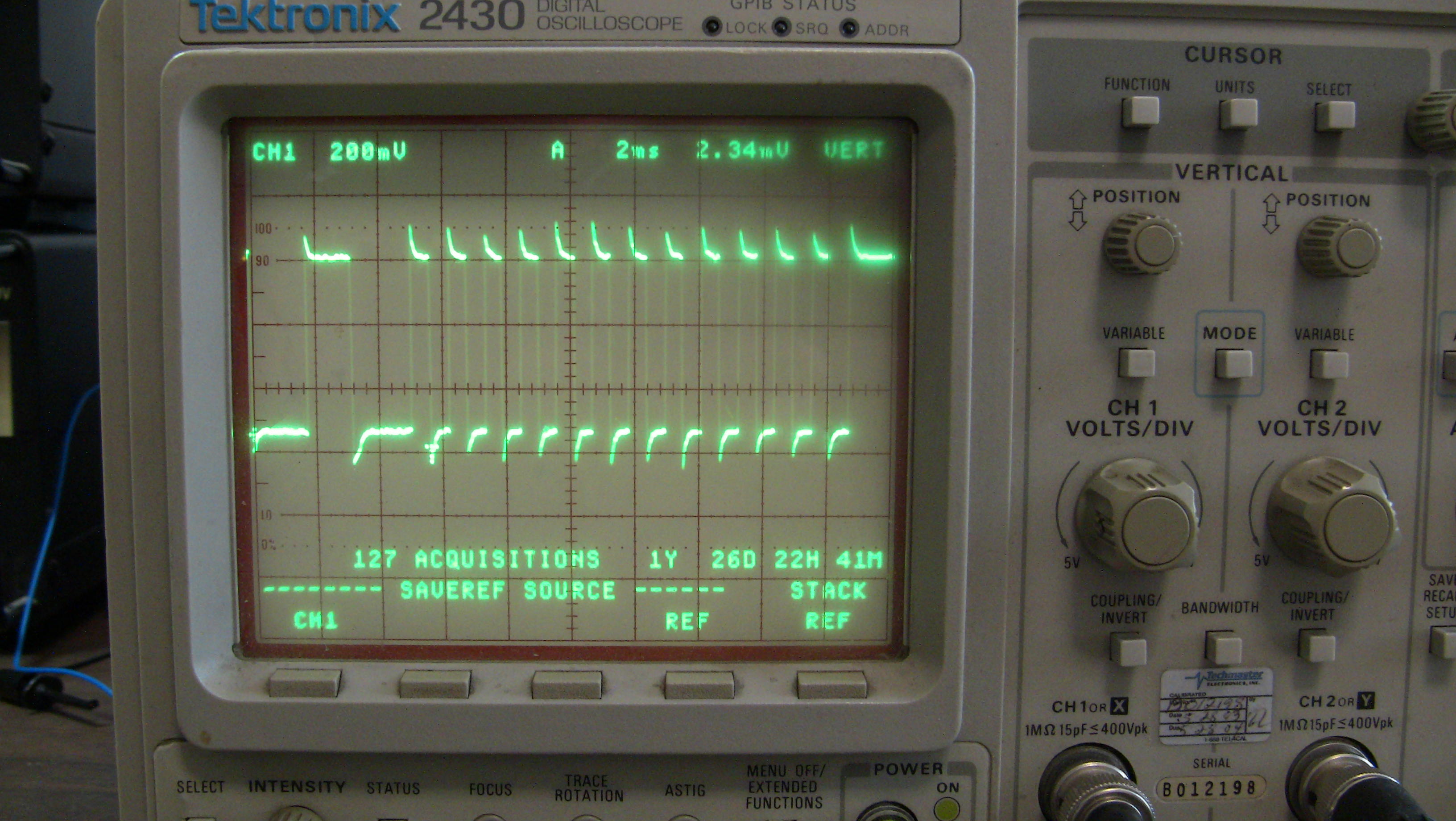
There are 12 pulse coming out from the lower sensor
every revolution.
Count 4 teeth and fire rotor two count 8 teeth
and fire rotor three.
Reset the counter on the top sensor occurrence
Very simple to do with one $1 CMOS 12V powered
counter chip.
With CD there is no dwell time so it will always fire at
exactly 22 degree before TDC.
I don't know why I did not think of this 15 years ago :)
No computer necessary. This generates the proper
triggers for the M&W CD ignition system.
Use the M&W to fire the coils. Six simple coils. Not RX8
or LS1 coils. Simple... old fashion coils.
TRIGGERING
Trigger input & coil output numbers (letters) indicate CDI ignition
sequence not cylinder number.
M&W Pro street CDI systems default to falling edge ignition. To
select rising edge ignition install a jumper wire between Trigger
Edge and Signal Ground pins. Where the ECU contains an inbuilt
igniter it may be necessary to use rising edge ignition. If CDI and
ECU trigger edges do not match timing will be erratic!
I learned about M&W from Jim Medere at Racing Beat. He is using it on
the 600 HP turbo 2 rotor time to climb engine.
Paul Lamar
http://jbperf.com/dual_VR/v2_**1.html<
http://jbperf.com/dual_VR/v2_1.html
This variable reluctance conditioner board takes the VR signal from the
CAS
and converts it to a single pulse of 5v that will consistently fire the
coil, or signal the computer that the timing point has arrived so the
computer can trigger the coil.
The
http://freeems.org/ guys have a system worked out very similar to the
megasquirt 3, but open- like when I told them what I was working on they
modified a couple of header files for me. They are using this system on
several different platforms, including all out race cars and trucks.
Fred and his associates are more than willing to help. I bought the
recommended board from Technological Arts and have started to put together
the system. The total cost looks like around $175 to 200. The recommended
board uses Xgate to handle most interrupt readings freeing the main
processor to run the engine.
I have another daughter board that optimizes the use of the lowZ peak and
hold injectors, however these guys recommend using the newer high
impedance
injectors. I may change over after I get it running.
The system already takes into account everything from idle to 8500RPM
(where my limiter kicks in at the moment) and will handle boost as well.
Mixture is handled through a lookup table.
Fred is also helping with a manual leaning system by inserting a pot input
in the header file- he wrote the base code and he has engines running in
race cars with it, so after telling him why I wanted it he agreed to stick
it in there. He wanted me to let him do it for now, so if it doesnt work
he
knows where to start looking for bugs.
Anyway, I have tested the vr chip and it indeed outputs a consistent
signal
of 5v, no rising edge no falling edge, no varying voltage with speed.
FYI, I bought the chips to make the board - the LM1815s- and while it did
work the resulting board was sort of big and I wanted it smaller if I
could. I also have extra surface mount versions, but these proved
difficult
to solder in place by hand. I was able to make the test board and prove it
worked before I ordered the little bitty unit. The unit I bought was
around
$30.00 and handles both CAS signals in one board.
As I have said before- my goal is a FADEC system with manual backup. This
VR board will fire the coils with only .2 amp input at 5 volts- even
without the EFI.
Kevin Alderman
Apples and oranges Kevin. This system uses no computer(s) of any kind. No
software. No bugs.
Pure digital hardware.
The trouble with "smart coils" like the RX8 and LS1 is they are not smart
enough.
They require dwell time. You turn them on wait 4 ms or longer they turn
them off
to cause a spark.
4 milliseconds is no problem at 500 RPM or 8.333 revs per second. It takes
120 milliseconds
to make one rev. Small timing error 4/120 X 360 degrees.
However at 8,000 RPM it takes only 8 ms or so to make one rev. The timing
error is
therefor NOW 180 DEGREES !!!!!!!!!
It is relative easy to use a computer to figure out how soon and when you
turn on and off
the "smart coil".
This system however does not require all the support stuff and cost that
goes along with any computer.
It will work with a two rotor as well. All you need is a decimal counter
to count to six.
It cost next to nothing.
Paul Lamar
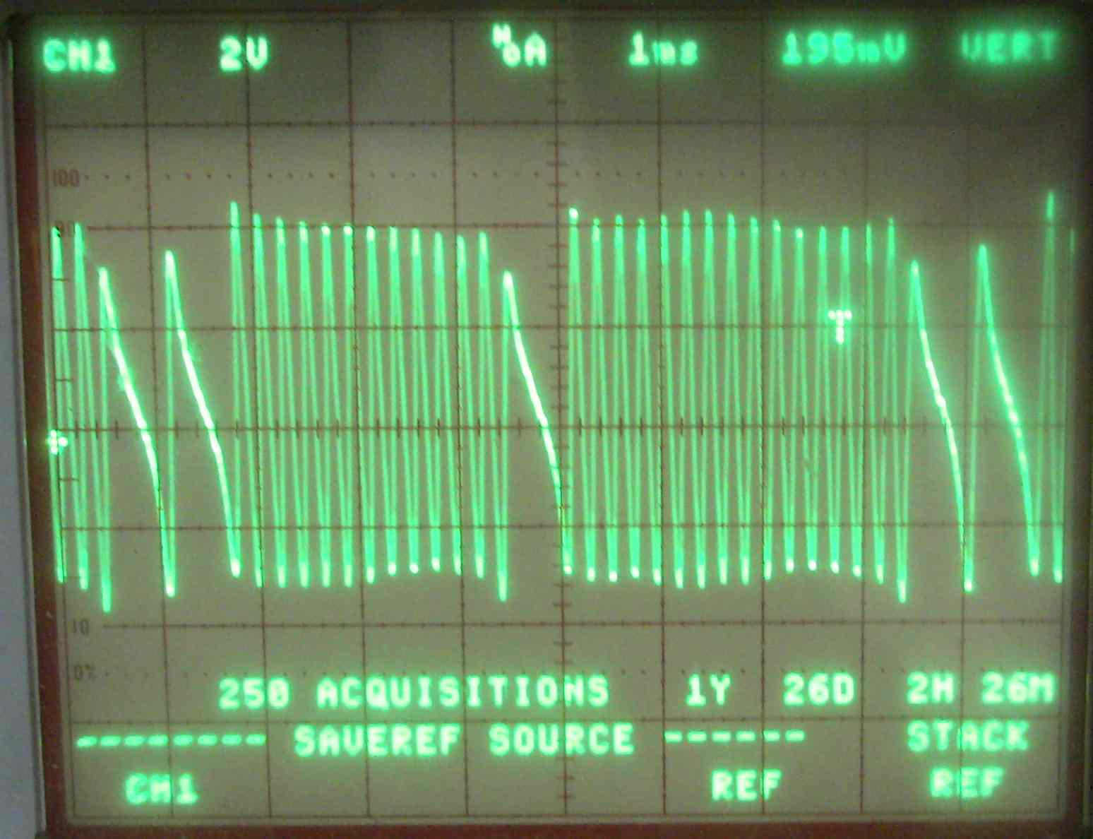
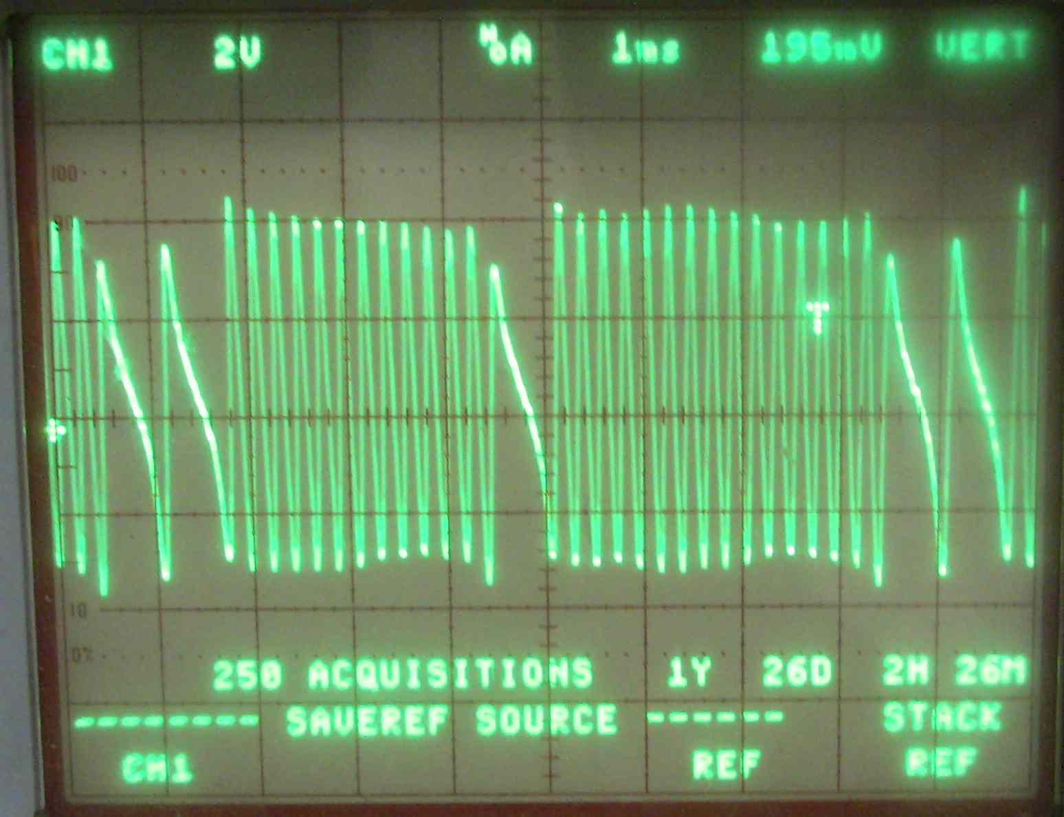
I understand that- if you remember when I was testing the CAS directly
attached to the coil trigger, I found that at speeds less than 400 RPM (800
engine RPM) the spark was intermittent. The more I tested, I found that
the voltage was low at idle speeds and very high at high engine speed. I
needed a solution that would fire the coils with no computer, and one that
would feed a computer. This does that. With a nominal 5v input, it will
fire the coils directly. Fed from the ECU, it will fire the coils when the
program dictates.
You don't need a computer to use this chip, it works quite well like it is.
I would guess that with the addition of a 7805 regulator to provide the
input voltage, you could use this with a carb and the factory CAS for a
very reliable system. I bought 2 and will run them like Tracys system- A
and B.
I am working on a "unique" system- a true FADEC with mechanical/manual
backup. While I am wanting to fly the plane, I want this system to work as
well and I know that if I skip it, it is unlikely I will take the plane
apart later to install it.
KA
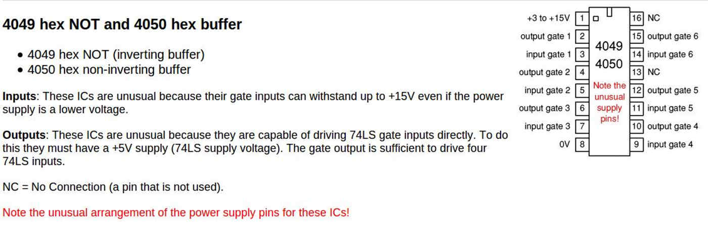
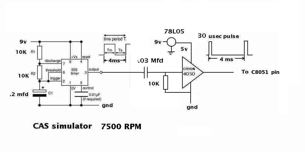
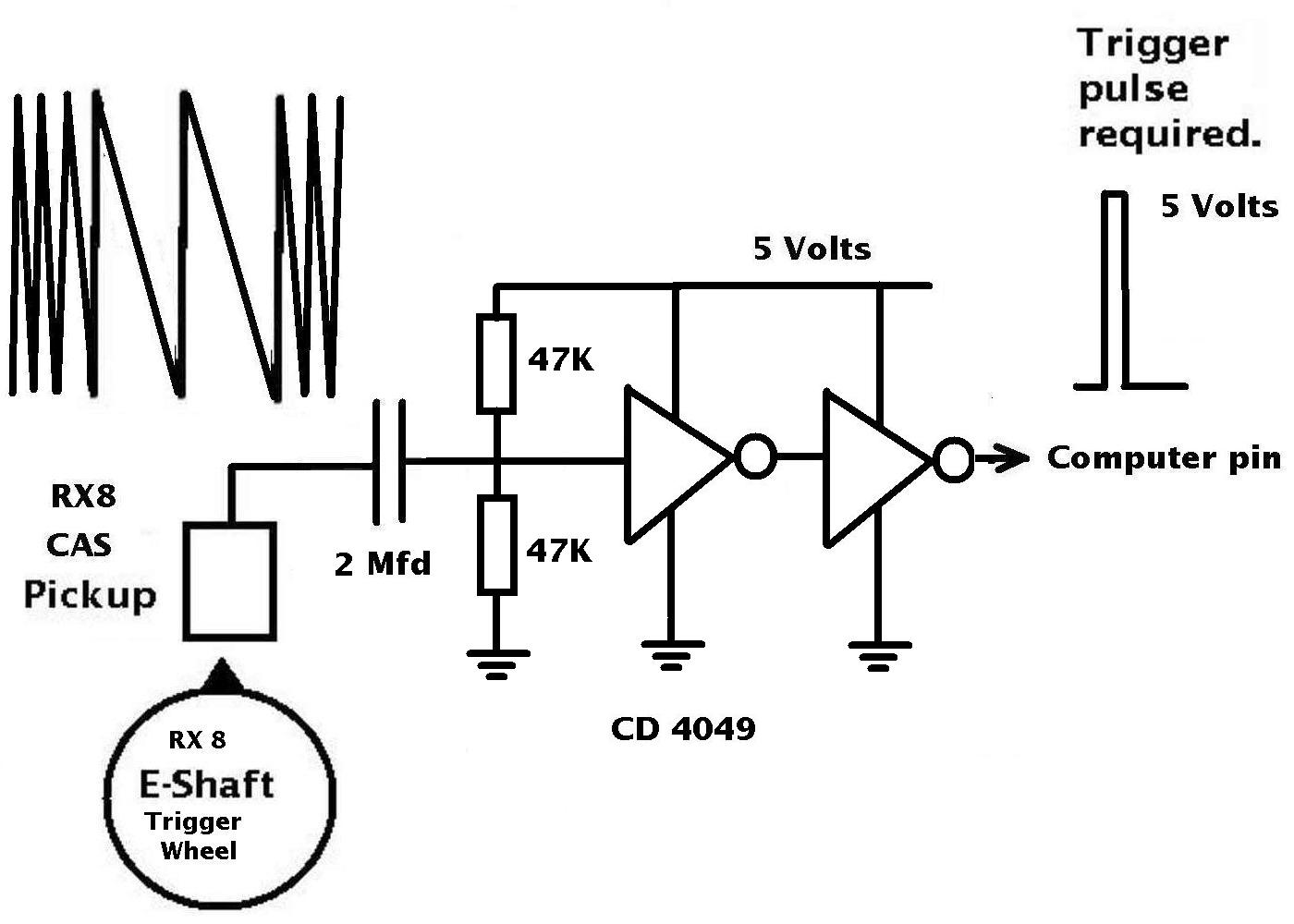
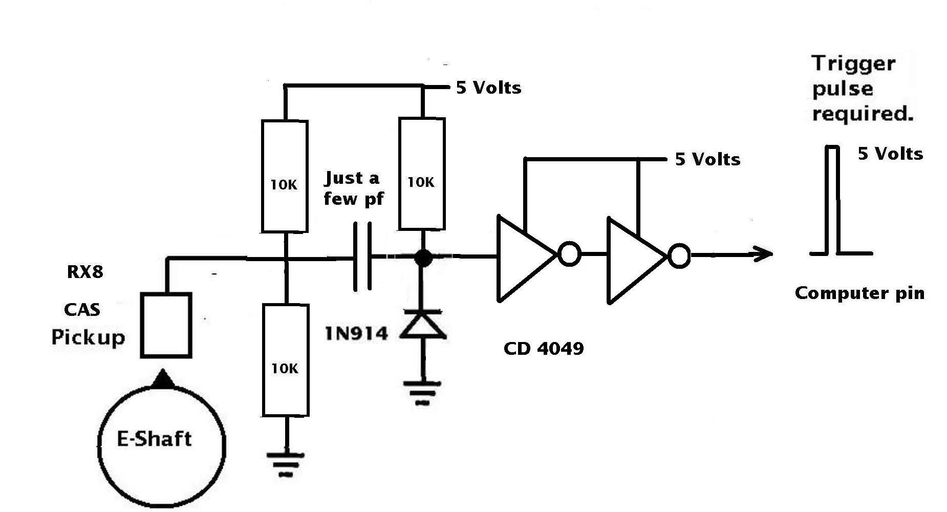
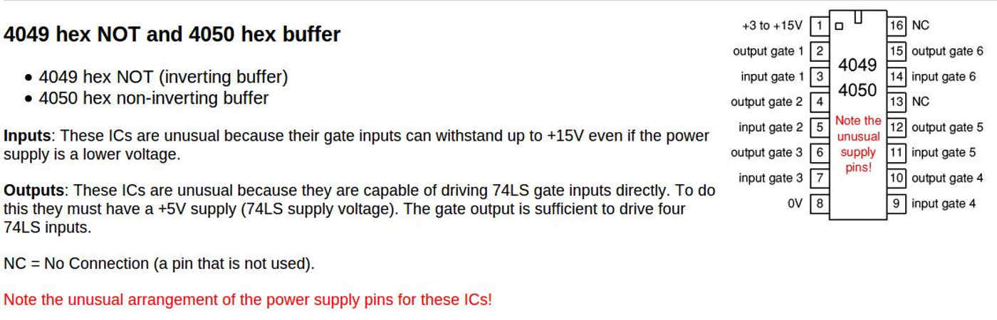
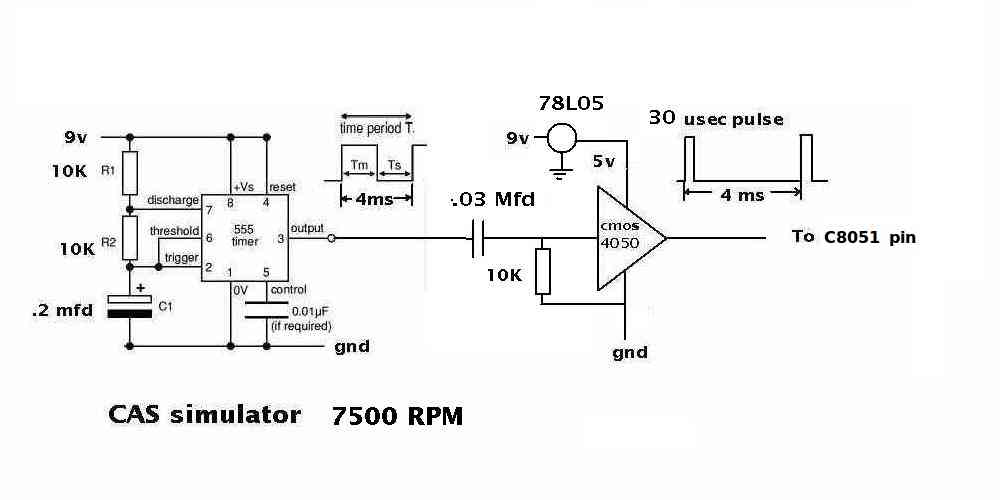
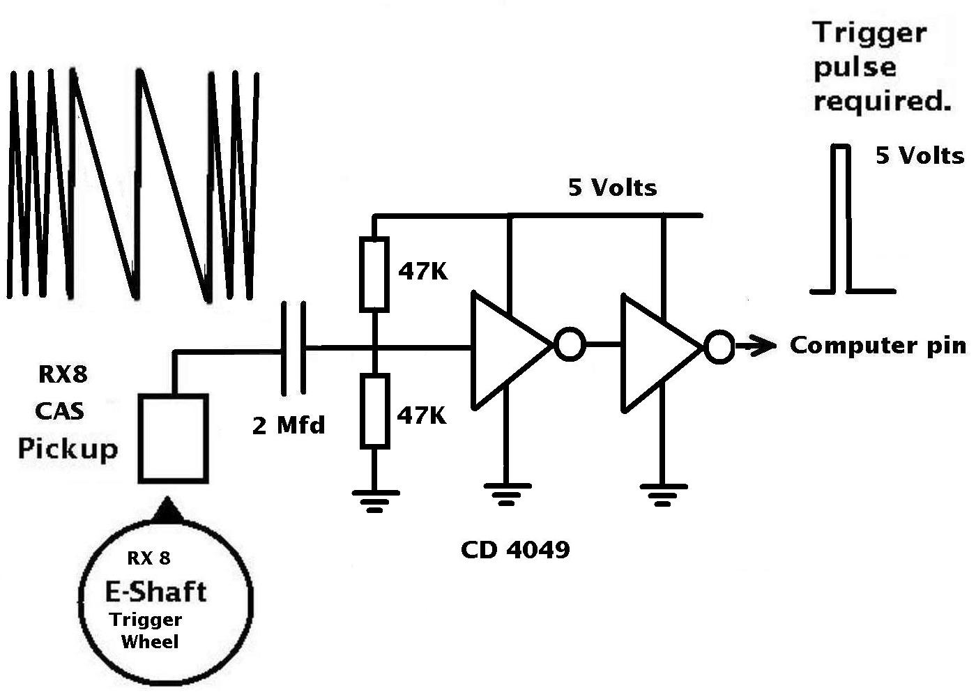
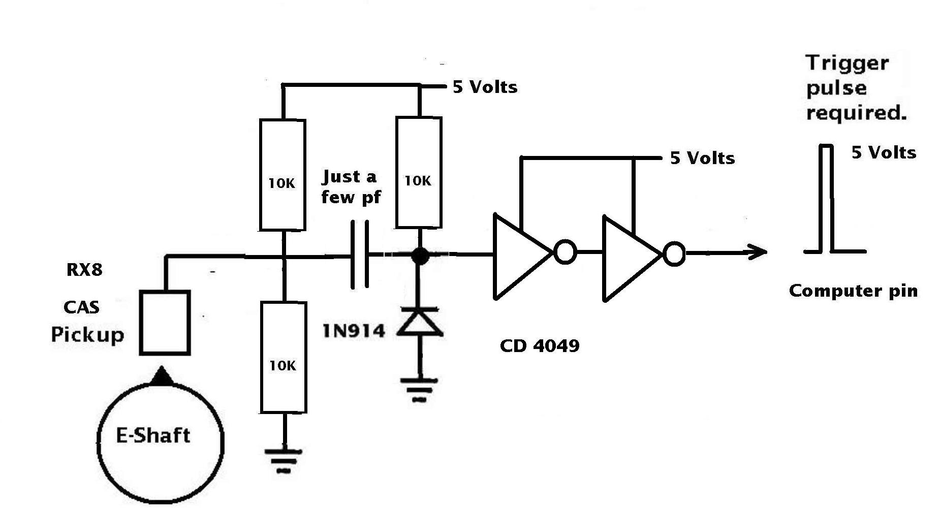
There are several ways of fixing that CAS problem with a $1 CMOS CD4049
or CD4050.
Paul Lamar