Paul,
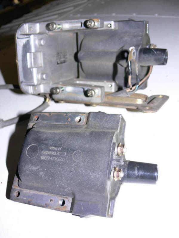
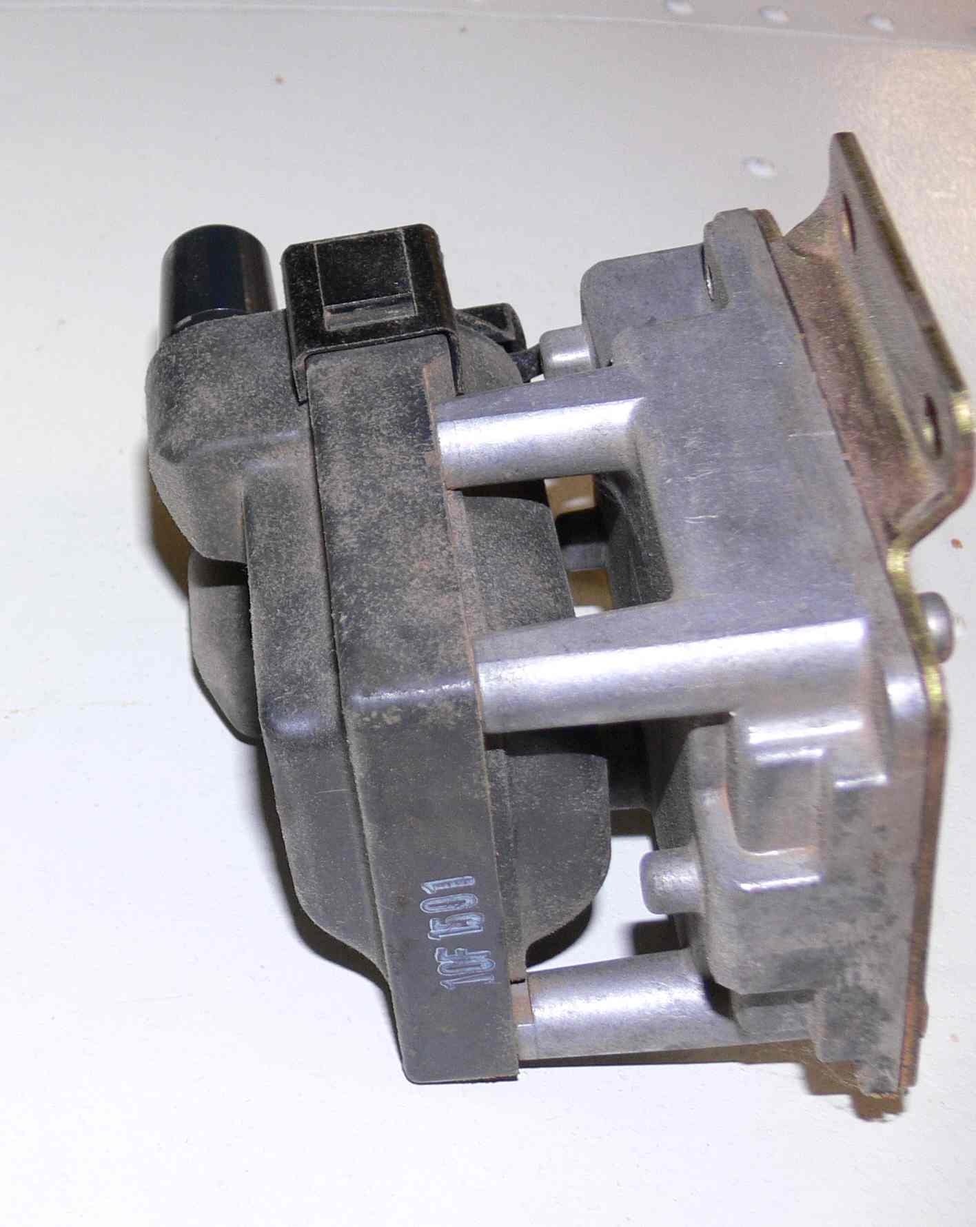
I have tested this already- if you have the stock (old style) coils
with ignitors here is what you need to make spark:
1.The VR boards that we emailed back and forth about earlier-
http://www.jbperf.com/dual_VR/__v2_1.html
<http://www.jbperf.com/dual_VR/v2_1.html>. One board is good for 2 CAS
pickups- you would need 2.
2. A board with 2 7805 voltage regulator chips and 3 FET
transistors.
The stock CAS generates the rising/falling signal to the VR board,
the VR board takes the 5v input signal and pipes a single 5v pulse
to the transistor, which turns on and allows the 5v signal to
trigger the coils. The 5v signal from the VR board should trigger
the coil to fire, but I would offload any current and possible
flyback to a separate board, and maybe add a flyback diode in there
just in case something goes wrong :).
If you have newer coils, just trigger the coils off of the FETs, and
leave the other the same. The VR board comes in an external
regulated and internally regulated version- the internally regulated
version has the regulator built in and will work off of the 12v
system.
If you have the coils, the boards are around $30.00.
KevinA
Kevin, do the VR boards send a narrow negative pulse to the
smart coils?
If so the smart coils are conducting current all the time except for
the pulse width.
The LS1 and RX8 coils have both overheated and failed.
In the old days that's how distributors worked. The coils were on
most of the time.
When the points opened the coil fired. If you turned on the ign with
out starting the
car the coils some times would get hot enough to burn your fingers
but they were
in a steel can filled with oil. That assumes the points where
closed.
One of the things you can do is use a 4 ms wide 555 one shot
negative pulse. That way
the coil is only on 50% of the time at 8000 RPM (roughly) and 75% of
the time
at 4000 RPM and 87.5% at 2000 RPM idle.
Paul Lamar
The Variable Reluctance boards take the (rising I think) signal from
the CAS and use it to trigger a short 5v pulse out. This pulse out
can either turn on a transistor i.e. PNP and drive the coil, or sink
the coil signal to ground i.e. NPN. The board only has a single
simple function- take the variable voltage/capacitance (reluctance)
rising/ falling peak signal from the CAS and convert it to a single
5v pulse. The coils that I have are the built in ignitor ones, that
are connected to 12v, with a 5v trigger. I tested the coils with the
VR boards and the CAS up to 3000 engine RPM (1500 rpm drill) and
with a board simulating 7500 RPM. The coils fired throughout the
range flawlessly. My only issue now with the coils is my discussion
with Fred about the coil unit not being able to reliably fire 2
plugs at once since one side is wasted spark and shouldn't be
firing.
The web page for JB Performance tells which part of the signal it
uses to produce the ignition signal. I wouldn't think it would be
important other than it would change the timing a slight amount from
one to the other.
My interest in these boards came from 1. reading the Megasquirt
boards and seeing the problems that a VR CAS causes in the
computers, 2. talking with Fred with FREEems about the same issue,
and 3. wanting a reliable way to fire the coils in the event of
complete ECU failure. This simple little board does that. You could
also build the board using an LM1815 chip, but this chip is a
through hole, and makes the unit way bigger. This thing is about as
big as a nickel.
My testing indicates that with the timing set at 22 deg BTDC, and
using these chips and the transistors, I can reliably fire the coils
on minimal power. Add in a mechanical/ manual fuel source and you
have a mechanical backup that will get you home, or at least to a
better landing area. I will do more testing as I get this second
plane done and get back to my first one with the 13b.
KA
Well then the coils are subject to over heat as it must be a
negative going pulse to trigger.
Unless there is a one shot in there the pulse width will be less
than one ms. Probably only
a few microseconds. Do you have a O scope? This is worse than a
distributor with points.
The "T" indicates a plug fire.
______________ _____________________________
.............| |
.............T__|
If it was a positive going pulse it would have to be longer than 4
ms to give the coils time to
charge or it would not work. That also involves a 555 chip.
.................._____
..................| |
__________________| T_______
Tracy went through a bunch of LS1 coils. He wound up with the the
truck version with heat sinks and
elaborate enclosed cooling system. I built a heat sink for the
RX8. All this is the sledge hammer approach
to the problem. The best thing is turn them on for 4 ms and turn
them off to fire. The max on
time is then 50% at 8000 RPM and 25% at 4000 RPM and much less at
idle. Way less current at cruise.
This reduces the current drain and gives you more time in case of a
alt charging failure.
Paul Lamar
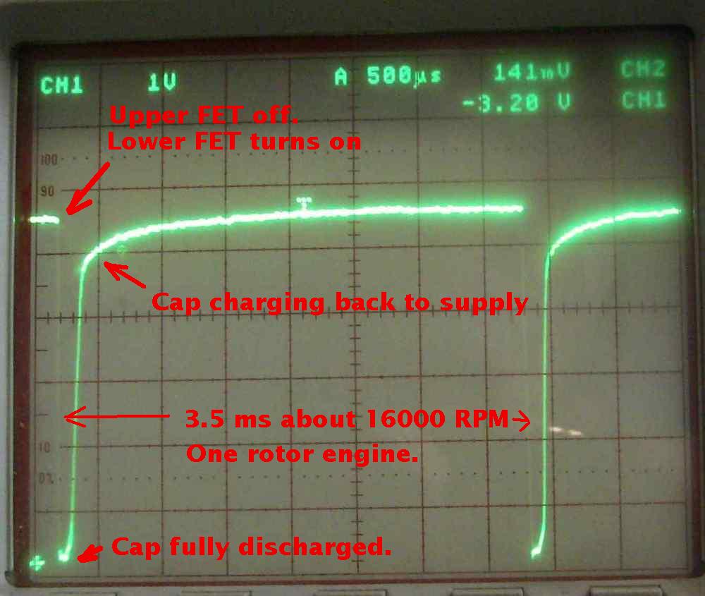
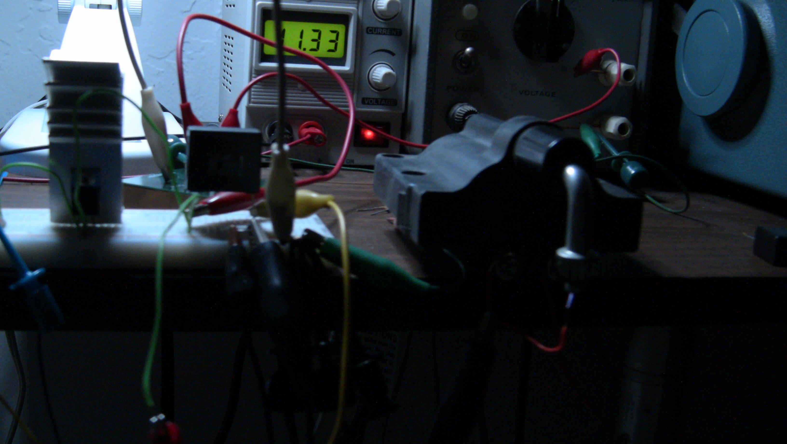
I do have an O scope, and have confirmed the 5v pulse from the VR board.
So far, however, my testing has been done with the coils that I have-
the old gen2 style. These have 12v in, ground and a 5v + trigger lead.
I haven't taken it apart, but I would have to assume that the system
charges and then sits and waits for the trigger signal. I would expect
that since the coil/ignitor is energized as soon as you turn the switch
on, the internal components take care of dwell time.
You might be interested in knowing that the FREEems system handles the
dwell through programming. And one day when I get time, I will get back
to that project.
KA
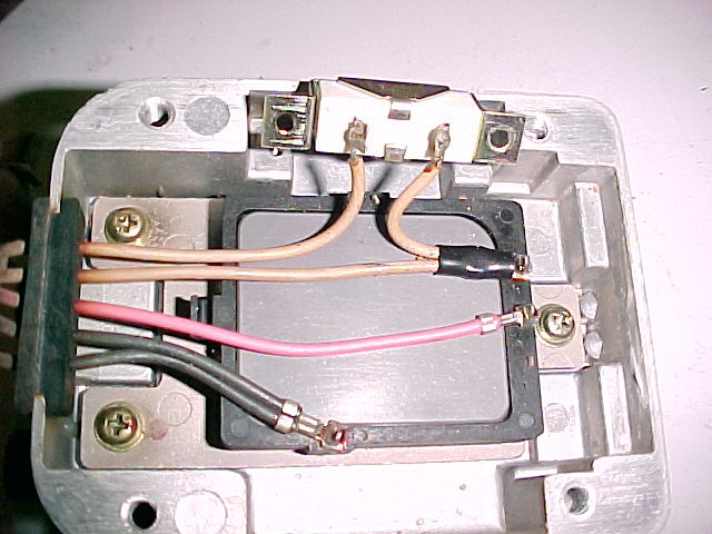
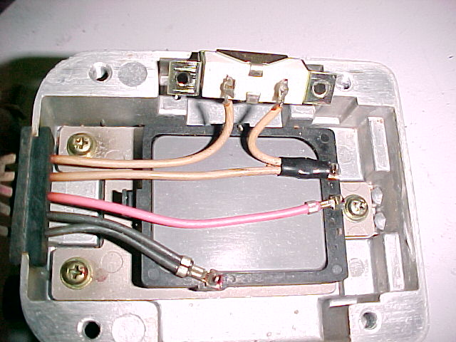
I have a set taken apart. I'll take another look at the igniter circuit
board in there. We had to increase the power rating on the ballast
resister back in the days Tracy's system was using them. That was prior
to the use of GM LS1 coils. I suspect the stock computer was doing a
better job of managing the current. I also suspect they are a lot more
robust than the LS1 and RX8 coils.
In the mean time measure the current they are using.
Paul Lamar