I am looking at using an Aeromatic wood prop. I know a guy that makes
these propellers and he has a lot of the original hubs to build props
from. He tells me that the 8 bolt pattern is not used much (I think
they were used on the Franklin engines) and he will let me come in
and build my own prop with one of these 8-bolt hubs. Will the Ross
copy PSRU's be built so that flange could be drilled to accommodate
the hub?
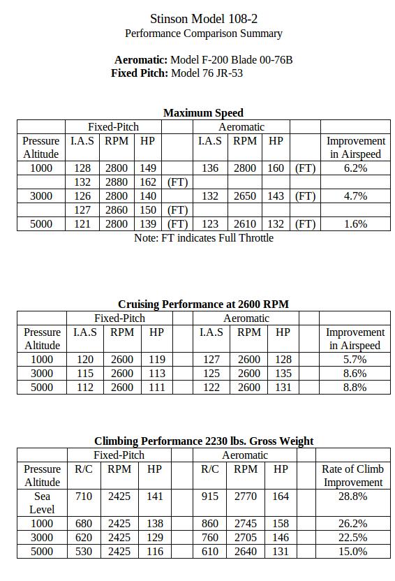
BTW. this guy has been experimenting with the original Aeromatic
design and he claims to have made some improvements that I think are
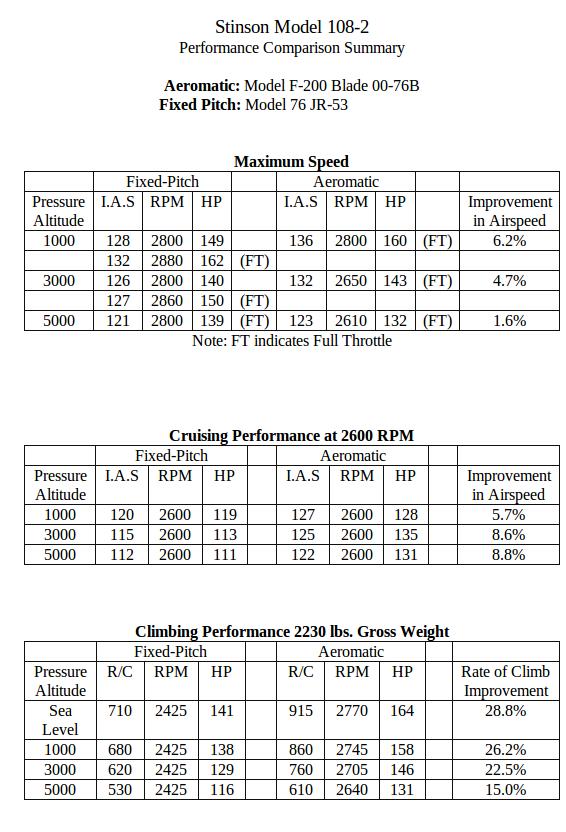
fairly significant. He claims that IF, IF the prop is adjusted
correctly and IF the engine is turbo normalized, he can make the prop
work exactly like a CS with the exception of no cockpit controller.
For non turbo normalized engines he has an altitude compensating
adjuster device that will automatically correct the propeller
adjustment to compensate for power loss at altitude. The altitude
compensating device has not yet been flight tested though. If all
this is true it might be worth looking at. No hollow crankshaft, no
prop governor, no electric controlling system. I don't know the
weight but he claims it is about half the weight of a CS. he sells
them installed for $5350. Not sure how this measures up to the
electric composite propellers.
Paul Shamlian
Yes I can do that as in the Ross design the prop flange is a separate
part.
Paul Lamar
Mr. Shamlian,
I would be very interested in contact information for this individual
who is improving the Aeromatic design. Thanks.
Gene Kahn
I know the guy. He is Kent Tarver
Tarver Propellers, LLC
1500 Rio Vista Dr. Hangar C-4
Fallon, NV. 89406
*PHONE* - (775) 423-0378
Zoltan Szakaly
-----------------------------------------------------------------------------------------------------------------------------------------------------------
What is an Aeromatic Propeller?
"The Aeromatic propeller is a fully variable pitch propeller that is
virtually equivalent to a constant speed propeller. But it is not quite
the same thing. The typical constant speed (CS) propeller for a Lyc
0-320 will weigh about 54 pounds, add to that the weight of a governor
and the cockpit control, you are pushing 60#. In addition to that, the
engine has to have a hollow shaft in order to feed the oil to the hub."
"The Aeromatic prop needs no governor, cockpit control nor a hollow
crankshaft. It is entirely controlled by dynamic forces, centrifugal
forces, air loads etc. The typical weight of the Aeromatic is about 34#.
That weight varies somewhat depending on which configuration of the
propeller you have. It will allow your engine to develop 100% horse
power for takeoff, climb and cruise. Typically when you apply full
throttle for takeoff you engine will rev up to about 50 rpm less than
red line. After you have reached flying and or climb speed your engine
will be turning red line rpm. After you reach cruise altitude and level
off and gain speed, the propeller will increase pitch as you gain
airspeed. Consequently you are now in cruise mode with more pitch much
like a constant speed prop. This is not a two speed prop, it modulates
itself based on the speed of the airplane and other dynamic forces. And
it is not going to cost as much as a constant speed prop. These
propellers were certified on most of the production airplanes during the
big airplane boom right after WW II. Pipers, Stinsons, Ercoups,
T-crafts, Bellancas, Swifts, Aeroncas, Cessnas, Meyers, Monocoupes,
Fairchilds, Grumman Widgeon, Johnson Rocket, Ryan Navions and more plus
some foreign airplanes."
These props will be especially useful on many home built airplanes in
the range of 40 HP or less up through some 260 HP engines. There are two
basic designs, one for flange shaft engines and one for 20 spline shaft
engines. It is a potential propeller for some 30,000 C-172 airplanes.
After reading a pilot report on Van's RV-9 with a Lycoming O-235, where
the test pilot almost begged for a constant speed prop, it occurs to me
that the Aeromatic would be an ideal propeller for that airplane/engine
combination.
OPERATION IN FLIGHT.
1. The stability of the Aeromatic propeller is obtained by balancing
the pitch decreasing effect of the aerodynamic force with the pitch
increasing effect of the net centrifugal force acting on the masses of
the blade and counterweight.
2. At take-off, the pitch decreasing forces are greatest and will,
therefore, move the blade forward to low pitch to permit the engine to
develop full take-off power.
3. During the climb, maximum power is made available due to the fact
that the blade pitch increases as the velocity of the airplane increases.
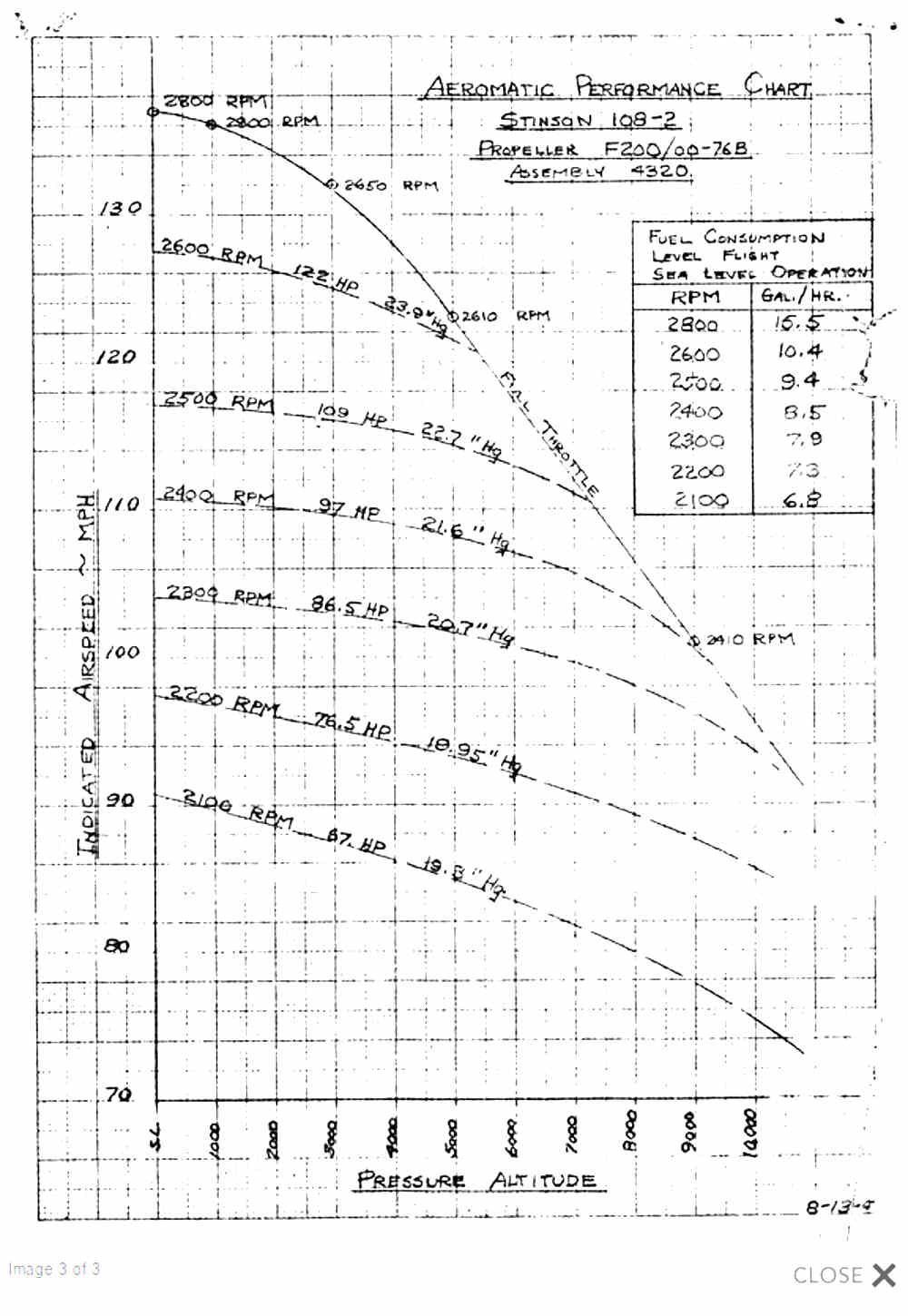
4. By maintaining given cruising rpm, constant horsepower of the
engine is available at altitude up to cruise critical (open throttle)
altitude.
INSTALLATION.
The Aeromatic propeller is a self-contained unit requiring no controls
from the propeller to the cockpit. The propeller is mounted on the
engine crankshaft in the conventional fashion using standard attaching
parts for standard mountings.
THE AEROMATIC IS ELIGIBLE FOR USE ON THE FOLLOWING AIRPLANES
Aeronca 7ac, 11ac, 11cc, s7ac, s11ac ---- Bellanca 14-13, 14-19 ----
Cessna 120/140, 170 ---- Commonwealth 185 ---- Ercoupe 415C, CD, E, g
---- Goodyear GA-2, -2B
Jamieson J-1 ---- Meyers MAC-125C ---- Monocoupe 90AF-100 ---- Piper
J-3C, J-5C, PA-11, 12, 14, 16, 18, 19, 20, 22 ---- Swift GC-1A, 1B ----
Stinson 108, -1, -2, -3
Temco TE-1A ---- Aero Design L-3805 ---- Cessna Airmaster 145, 165 ----
Fairchild 24W, 24R ---- Grumman G-44, A ---- Johnson 185 ---- Monocoupe
CW ---- Navion 185, 205, 260
Stinson L-5 ---- Aeronautica Macchi MB-308, 320 ---- Auster Autrcrat J5
---- Auster MK V ---- Desford Trainer ---- Fokker F-25, S-11 ---- Karhu
48 ---- L'Aronautique S-90
Lark KZ-VII ---- Nord 1200 ---- Piaggio P-136 ---- Pilatus P-4 ---- SAAB
91 ---- Iberavia I-11 ---- Culver LCA, LFA and others.
Comments
TARVER PROPELLERS, LLC owns the rights, engineering, tooling and Type
Certificates for the above propeller and propeller blades. We are
located on the Fallon Municipal Airport (FLX). You are welcome to stop
by for a visit. Our facility is located on the NW side of the runway
just a few yards from the crop duster Frey Sprey.
If you want to look up the TC's, here they are: For Aeromatic, TC 820
and 833."
Unfortunetely there was one blade failure in the past, almost certain
caused by a prop strike that lead the FAA to issue a SAIB regarding
Aeromatic propellers. Initially issued in 2001, the final wording can be
found here NE-01-23R1.pdf
For those that can't load that file , read throught the SAIB here.
And finally a message from Kent to his fellow pilots. Why sugar makes
you not only fat but also sick.
Terms of Use | Disclaimer | About Us
Frequently asked questions
How do you set up an Aeromatic prop?
This answer explains what you would typically do assuming your prop has
been set up for your specific airplane/engine combination.
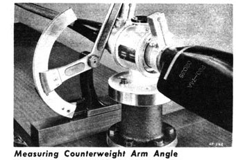
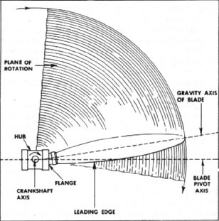
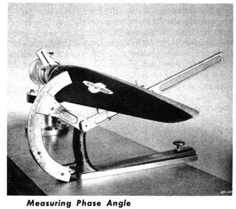
Technicalities: The Aeromatic F200 has 4 angles to be set. These angles
vary across the spectrum of airplanes.
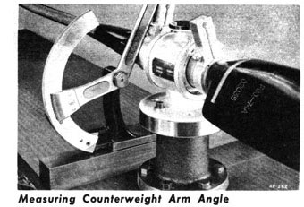
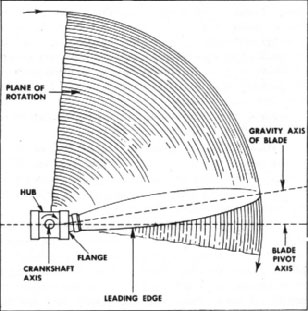
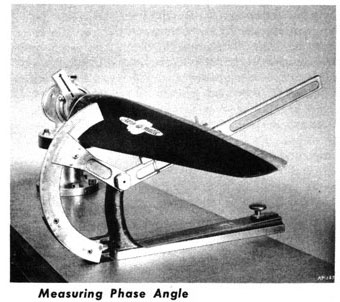
These angles are; Phase angle, Counterweight arm angle, Low pitch angle
and High pitch angle.
The high pitch angle is fixed and can't be changed because it is a
function of design. These angles are set at the factory. In the field
the installer may or may not have to change the low pitch angle.
There is another adjustment that may or may not need to be done by the
installer in the field. That is the amount of counterweight needed.
Theoretically everything should be perfect!
In other words, all of these angles and the amount of counterweights are
set at the factory for KNOWN airplane applications. The history of the
Aeromatic propeller shows that most of the time the factory settings are
correct and the owner in the field needs only to make checks to verify
the settings are correct.
The Aeromatic is designed so that at cruise the blade angle is at or
close to the phase angle, in static full power it is at the low pitch
angle, in a dive it will move toward the high pitch angle. These props
have on average, about 18 to 20 degrees of blade angle change. However
only about 4 to 7 degrees are used for all flight conditions. The extra
high pitch angle is there to prevent over revving in a dive.
Note: I strongly recommend that you use a calibrated tachometer.
Mechanical tachometers are notorious for being off calibration. Believe
me, 200 rpm error is not at all uncommon. Also your propeller most
likely will not perform correctly unless your tachometer is correct.
Furthermore you can easily put your propeller into a dangerous vibration
mode with a faulty tachometer. Calibrate your tach or buy that little
hand held battery operated tachometer to do your rpm testing. If you
send your propeller back to me with damage I guarantee you that I can
tell if you have damaged it due to vibration.
THE AEROMATIC F200 (for flange shaft engines up to 180 hp) A. Static
full throttle regulation procedure. Assume a C-125* engine on a Swift
with red line at 2500 RPM.
1. Remove all counterweights, bolts and nuts from the counterweight
arms. Do not remove the counterweight arm clamp bolts.
Check static full throttle RPM. If it is not 2500, correction can be
made by use of low pitch stop adjusting shims located under the
synchronizer cover plate.
Remove the six screws and remove the cover plate. See note 1 below.
One shim of .016" will change RPM by about 50. Removing a shim will
decrease RPM adding a shim will increase RPM. Do not add or remove more
than one shim at a time.
If you can't get the right RPM by removing or adding a complete shim you
can make finer adjustments by peeling the shims. See note2 below.
After reinstalling the counterweights in their original position you
will see a slight decrease in full throttle static RPM. This is normal,
DO NOT make any more adjustments on static RPM.
Note 1. You may loose some oil by removing the stop bolts. Catch the oil
in a container and replace it after you finish with the static rpm
adjustments. Doing the ground runs with less than full oil will not hurt
the propeller.
Note 2. The shims are peel shims. The shim is made up of .002"
laminations. Therefore you can make finer adjustments to RPM.
B. Flight RPM Correction and Altitude Adjustment for Original Regulation.
1. With the counterweights install and secured properly make a full
throttle level flight as close to your airport altitude as safely
possible. Engine speed at full throttle level flight should be 2500 RPM.
2. If you find that the RPM is 2600, add one -2 counterweight to each
side. This will reduce the RPM by close to 100. A -1 counterweight will
reduce RPM by close to 50. If your RPM is 2400 you must remove one -2
counterweight from each side. All flight adjustments are done by adding
or removing counterweights. You do not readjust your static RPM.
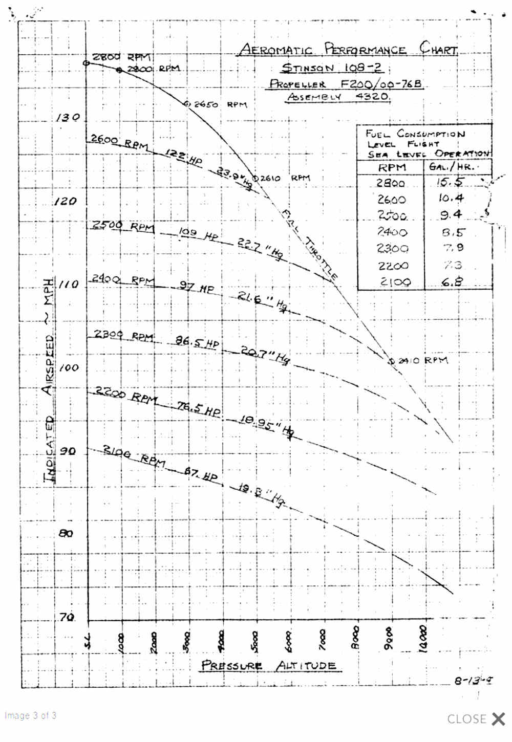
3. Aeromatic propellers will decrease full throttle RPM by about 20 for
each 1000' increase in altitude. If your home base is at 3000' you would
adjust your full throttle level flight RPM to be 2440. This will give
you the best all around performance.
Note 1: If you have your propeller set up for home airport of say 3000
or 4000' MSL and you decide to fly and land at an airport at sea level
you should be careful on takeoff from that field that you do not over
speed your engine. If you move your home base to a sea level airport
after having adjusted RPM for a higher airport you should re-adjust RPM
by adding or removing counterweights. The late Art Scholl, a renowned
aerobatic pilot, used an Aeromatic prop on his 200 hp Ranger powered
Chipmunk. I have heard that he would carry a small kit of extra
counterweights so he could make adjustments for the altitude at which he
was performing.
* An Aeromatic propeller that has been factory set up for a Swift with
C-125 does not use the same angle settings as used on a PA-20 with a
C-125. So, you can not just take a prop from a Swift and bolt it on a
PA-20 just because it uses the same engine. The difference in the speed
of the airplanes demands different angle settings.
THE AEROMATIC MODEL 220 (for spline shaft engines up to 260 hp perhaps
more in experimental airplanes)
The setup and adjustment procedure for the model 220 is the same for the
model F200. The only difference is in the way, mechanically, the pitch
stops are designed. The 220 uses four pitch stop bolts, two for high
pitch and two for low pitch. Each blade has it's own high pitch and low
pitch stop bolt. There are peel shims under the head of each stop bolt.
If you have to make static rpm adjustments follow these instructions.
1. Remove the counterweights, bolts, washers and cotter pins. DO NOT
REMOVE THE COUNTERWEIGHT ARM CLAMP BOLT. Do a static full power run. It
should be at red line rpm. If it is too high you remove shims under the
low pitch stop bolt heads. (These bolts are marked 1L and 2L, the other
two bolts are marked 1H and 2H.) You must do the same to the both
blades. If the rpm is to low you add shims. After you get the static
full power rpm correct, secure the bolts with safety wire and be sure
that the seal is good. Permatex #2.
CAUTION: These stop bolts carry virtually no load. They merely provide a
stop for the blade pitch. Even though they are 3/8" bolts do not torque
them to the 3/8" torque specification. Just make sure they are tight
enough to provide a good seal.
Note: 1. You may loose some oil by removing the stop bolts. Catch the
oil in a container and replace it after you finish with the static rpm
adjustments. Doing the ground runs with less than full oil will not hurt
the propeller.
Note: 2. As on the F200 propeller you will not be adjusting the high
pitch angle. Your propeller likely will never go to the high pitch stop
position.
2. From here you will use the same procedure to adjust flight rpm as
detailed above for the F200 propeller.
Spitfire and wooden props?
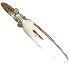
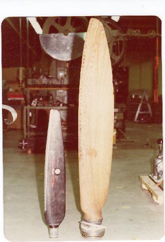
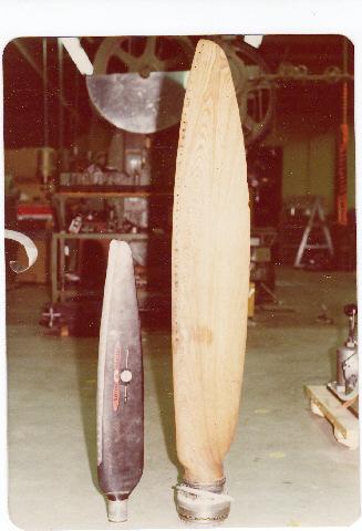
The early Spitfires and Hurricanes were delivered with adjustable wooden
props. Here is one pictured in comparison to an Aeromatic blade. As a
matter of fact the lag screws that holds the metal ferule on the wood is
the same design in both the Spitfire and the Aeromatic. So, the design
is a sound one.
The Rotary Engine News Letter. Powered by Linux.
ACRE NL web site.
http://www.rotaryeng.net
You Tube
http://tinyurl.com/beqqxas
Copyright 1998-2013 All world wide rights reserved.