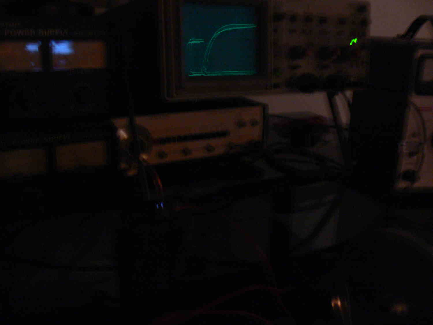
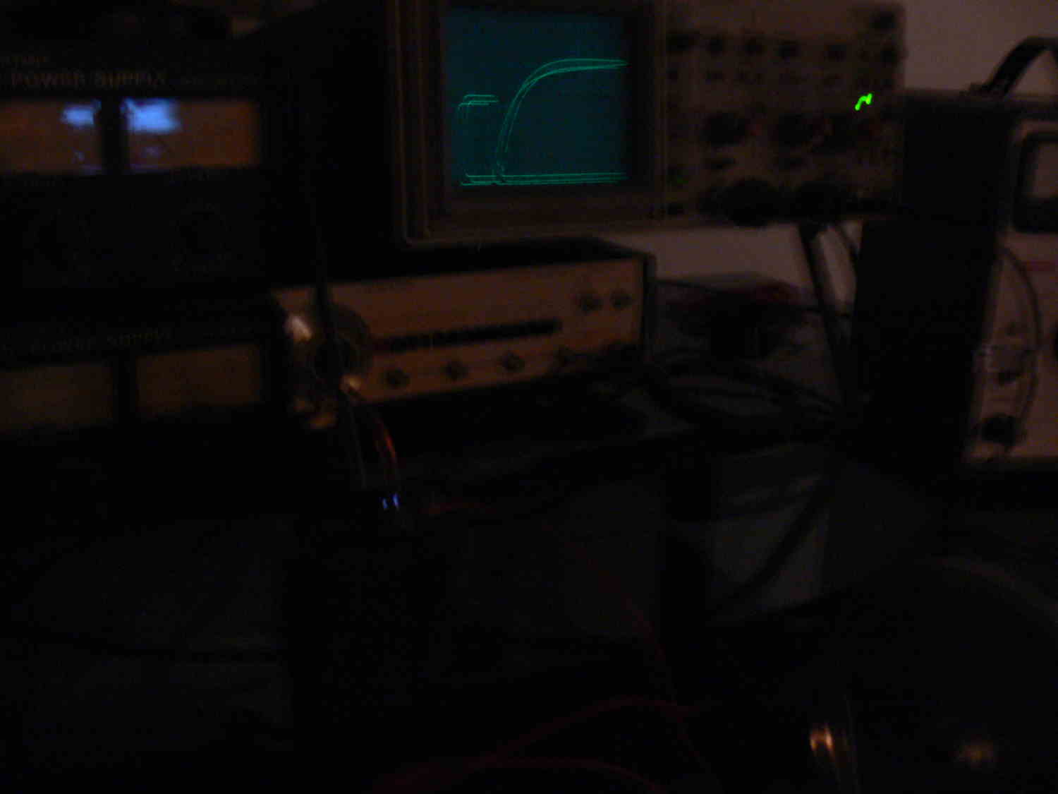
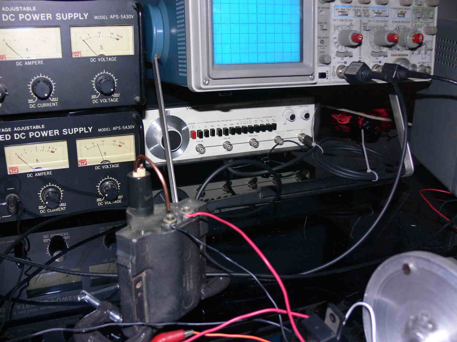
I cut the voltage to 420 from 560 because I have not received the 650
Volt 1 mF
capacitors yet. This is about 1000 RPM. Watch the movie and you can see
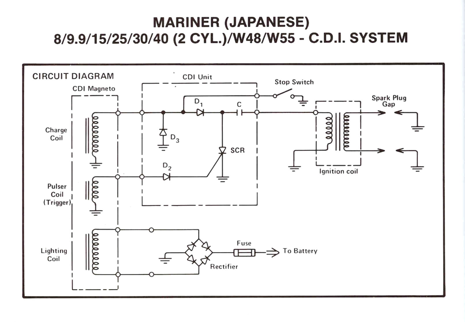
the blue flashes in the middle of the screen. The circuit is basically
the same
as the outboard/Vespa circuit but the high voltage power supply works off
a 110 volt wall socket instead of a charging coil. I am using the latest
hi tech solid state switch called an IGBT instead of an SCR shown in the
outboard schematic.
IGBT Insulated-gate bipolar transistor is a three-terminal power
semiconductor device
primarily forming an electronic switch and in newer devices is noted for
combining
high efficiency and fast switching. It will dump up to 50 amps through
the coil primary
winding in less than a microsecond. The coil is basically used as a
pulse transformer
so it runs much cooler than when used in an inductive mode. It also
fires immediately so
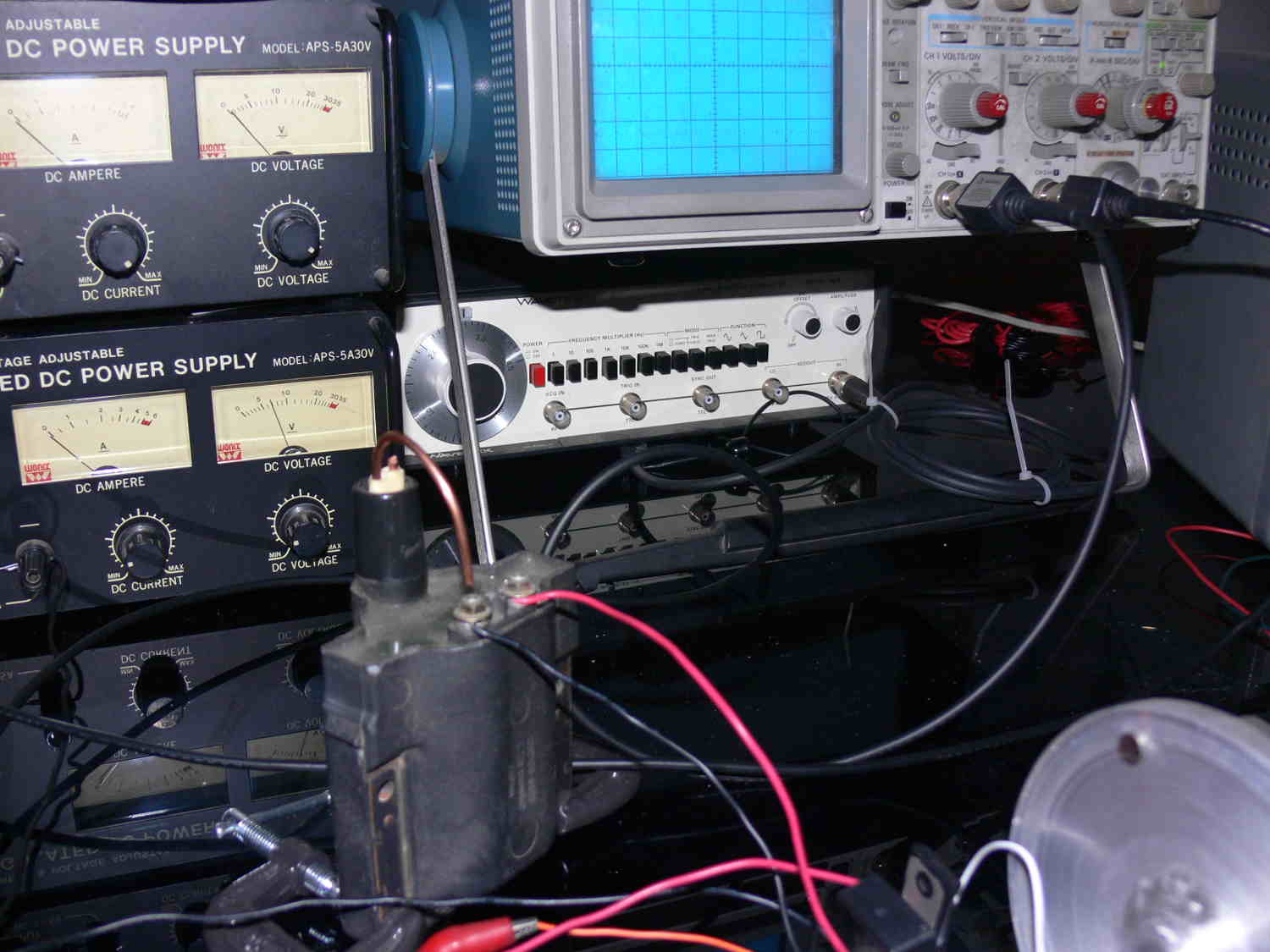
there is no dwell time needed. In this set up I am using a stock 2nd gen
Mazda coil
with out the igniter.
The 1 mF 450 Volt cap is charging through a 1.5 K resistor hence the
visible charging curve
you see on the O-scope. This high value resistor may not work at the
higher RPM's but
prevents the IGBT from shorting the high voltage supply. I plan to
experiment with a choke instead.
Paul Lamar
The Rotary Engine News Letter. Powered by Linux.
ACRE NL web site.
http://www.rotaryeng.net.
You Tube
http://tinyurl.com/beqqxas.
Copyright 1998-2013 All world wide rights reserved.