I cut the voltage to 420 from 560 because I have not received the 650
Volt 1 mF capacitors yet. This is about 1000 RPM. Watch the movie and
you can see the blue flashes in the middle of the screen. The circuit
is basically the same as the outboard/Vespa circuit but the high
voltage power supply works off a 110 volt wall socket instead of a
charging coil. I am using the latest hi tech solid state switch
called an IGBT instead of an SCR shown in the outboard schematic.
IGBT Insulated-gate bipolar transistor is a three-terminal power
semiconductor device primarily forming an electronic switch and in
newer devices is noted for combining high efficiency and fast
switching. It will dump up to 50 amps through the coil primary
winding in less than a microsecond. The coil is basically used as a
pulse transformer so it runs much cooler than when used in an
inductive mode. It also fires immediately so there is no dwell time
needed. In this set up I am using a stock 2nd gen Mazda coil with out
the igniter.
The 1 mF 450 Volt cap is charging through a 1.5 K resistor hence the
visible charging curve you see on the O-scope. This high value
resistor may not work at the higher RPM's but prevents the IGBT from
shorting the high voltage supply. I plan to experiment with a choke
instead.
Paul Lamar
Congratulations on the spark!
Henry
Thanks henry. What do you think of putting a diode across the coil to
aglow the coil to ring?
Paul Lamar
Paul,
I assume that you are using a circuit similar to the Mariner
Ignition. I also assume that you are thinking about back emf,
creating a high voltage spike at the end of the discharge cycle. I
would say that you can add a diode to prevent high voltage on the
cap, but I don't think you have too much of a problem as capacitors
can discharge most of its energy rather quickly. Once the energy is
discharged, and used up immediately as a spark on the secondary side,
the remaining voltage, and current, if any, from the capacitor should
be limited, and it can be dissipated through the primary winding to
the ground rather quickly. Especially when you notice that there is
not much heat building up on the coil.
So my two cents: The ringing is most likely a minor issue, but it
does not hurt to add a diode there.
Henry
Yes on the Mariner circuit. Here it is. IGBT instead of SCR.
Paul Lamar --
Paul,
You are still sending the Mariner circuit. :) Don't worry, I think my
conclusion is still valid. Even if there is ringing induced voltage,
the path to ground via the coil should still take care of it.
Henry
That is what I am using except for the charging coil.
I am slowly coming to the conclusion that a power resistor in series
with the high voltage supply is a good thing. About 1.5 K seems about
right for 8,000 RPM. Allows the 1 mF caps to charge but stops shorting
the HV supply to ground.
Paul Lamar
Yes, it is a better design to be able to control current flow with the
resistor. Or, you may want to put a coil in there to limit the current
when the IGBT turns on. The value of the coil depends on your turn on
time. And yes, if you do this, you definitely wants to protect your
circuit with a diode.
By the way, is there a way to modify the circuit so the IGBT is placed
between the coil and the ground, with the capacitor feeding the coil
directly? The coil can then be turned on for a short time, creating a
single spark on the secondary. If the on time is short enough, say equal
to time constant of the circuit, then we will never be shorted directly
to ground.
Actually, just how long is the discharge time for the spark? If it is
short, you may want to use 555 to create a sequence of pulses.
Let's say a two stage circuit, with a first 555 setup as a one shot
timer, triggered by the hull effect sensor and the second one enabled by
the first one to give multiple sparks? Would it help to ensure ignition?
Henry
If you place the IGBT between coil and ground the cap would not charge
with the IGBT off.
You could use two IGBT's. One on for charging the coil and off for
spark. The other for spark.
I don't know on the discharge time but the IGBT stays on controlled by
the hall effect sensor.
Right now about one or two ms. You would have to charge the 1 mF cap
between pulses.
That might be possible at 7500 RPM with no resister in series with the
HV supply.
MSD seez that it is not.
As an alternative go down on the cap value and hope you still have the
energy with
560 Volts.
Paul Lamar
Paul
One thought that I keep having in relation to the Turbo Compound test.
Wouldn't it perhaps be a good idea to have available a standard spark
setup so as to compare with a known benchmark (standard 20b twin must be
known by Mazdatrix).
Then add your new ignition to see what performance benefit it brings at
say higher RPM?
If the ignition does have meaningful benefits you won't know if it is
the Turbo Compounding or the ignition?
Steve Izett
As long as I use the same ignition for TC and non TC it matters
not. We are not looking for the best BSFC non TC. We just want
a back to back comparison. TC non TC.
Paul Lamar
Just to prove the waste spark works I hooked it up to a 2nd gen waste
spark coil.
The plan is to fire upper and lower plugs at the same time with a waste
spark coil.
Thanks for the waste spark coils Kevin.
Paul Lamar
OK. I'll bite. Could you explain "aglow" and "ringing"?
Dale Davies
aglow was a typo... should have been allow.
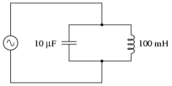
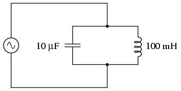
Inductors, when connected to a capacitor form a combination called a
tank circuit.
This tank circuit has a resonant frequency. . When shocked
or perturbed they "ring" sort of like a bell when it is struck.
http://www.allaboutcircuits.com/vol_2/chpt_6/2.html
"A condition of resonance will be experienced in a tank circuit when the
reactances of the capacitor and inductor are equal to each other.
Because inductive reactance increases with increasing frequency and
capacitive reactance decreases with increasing frequency, there will
only be one frequency where these two reactances will be equal. "
When I was in the US air force stationed at a radar station in Ramore
Ontario back in the 1950's I studied radio maintenance by
correspondence with the US air force college. I got a score on the test
administered by the base adjutant lieutenant of 147 out of 150. Just
the two of use were in the room. He accused me of cheating some how :)
Paul Lamar