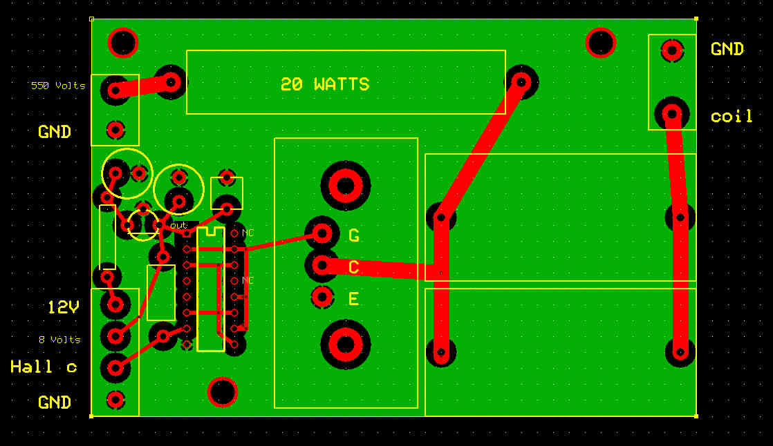
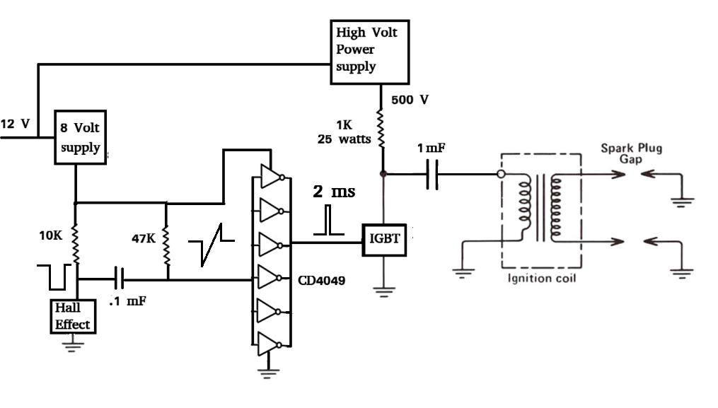
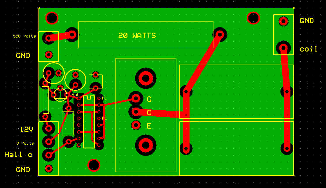
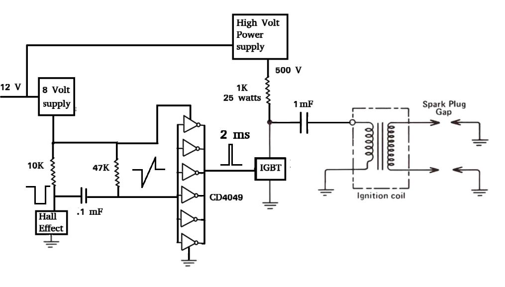
I had to add a .1 mF and a 47K resister.
I suddenly realized that in the remote chance a magnet stopped in front
of a hall sensor
the IGBT would stay on and burn out the 1K 25 watt resister or maybe destroy
the high voltage power supply or IGBT. Something would have failed.
The 47K/.1 mF combination circuit is called a half one shot.
It will not pass DC. The engine must be turning over however slowly for
it to work.
That is one thing Hall Effect sensors do that VR CAS sensors do not do.
Not enough however, to not use Hall Effect CAS sensors :)
They put out full pulse voltage at near zero RPM.
Paul Lamar
-------------------------------------------------------------------------
The 8 to 40 volt input 300 Volt DC out high voltage power supply can be had
direct from Linear Technology for $125
http://www.linear.com/demo/dc1322a
I bought one and will test it as soon as I get it.
I plan on using it for the RV4 stand alone CD ignition
system.
I can make it for less than this.
There are several CD ignition options for a 2 rotor..
In order of redundancy and cost.
1.One power supply, two CD modules, two waist spark coils. Lowest cost.
2.Two power supplies, two CD modules, two waist spark coils.
3.Two power supplies, four CD modules, four simple spark coils.
4.Four power supplies, four CD modules, four simple spark coils. Highest
cost.
Paul Lamar
The Rotary Engine News Letter. Powered by Linux.
ACRE NL web site.
http://www.rotaryeng.net.
You Tube
http://tinyurl.com/beqqxas.
Copyright 1998-2013 All world wide rights reserved.
-