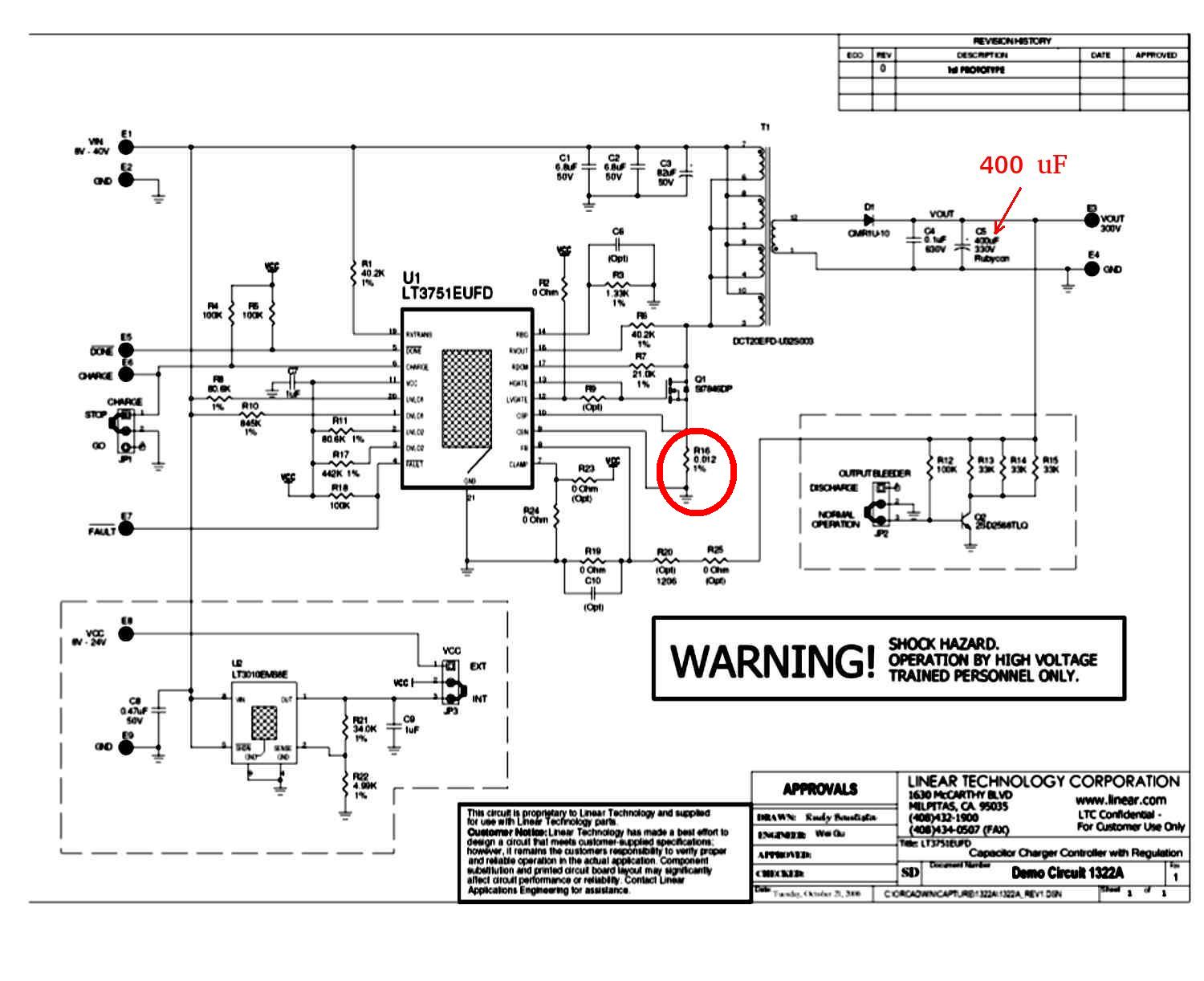
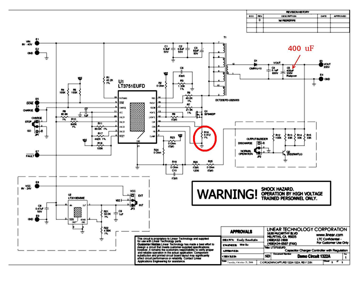
It works! This is the modular HV power supply for the modular CD ignition.
Everything from one power supply and one CD module per spark plug down
to one power supply per engine and one waste spark coil per rotor.
Thanks to all the smart people on here that have helped.
Thanks to my wife Robin for putting up with my 16 hour a day work habits :)
It has been a mount Everest learning curve.
The IGBT is running at about 80 F and the input voltage for
the power supply is 8 volts for the scope picture shown.
With no load input current is less than a tenth of an amp.
The scope is set to 50 volts per division so what you are
seeing is 350 Volts peak. That varies with pulse width and
output current will vary with frequency.
The time base is 10 usec per division.
The osc is running at 40Khz.
The IGBT is the same one I am using in the CD ignition modules.
The coil is the same one Lin Tech uses.
The idea here is to use a sledge hammer IGBT.
Parts cost less the PC board is less than $20.
No tricky, expensive and troublesome LSI chips :)
CMOS 555's and 4050's are less than $1
All this is initial. Pulse width is manually adjustable as is the frequency.
I am very relieved. It has been looking bad and too hard to do for years.
Paul Lamar
Paul
I ran some approx calcs and you may have more than 20A pk in the pri
winding. Its important to know the pri current. A sense res in the
emitter will work but it would be in the 5-10m Ohm range. The classic
waveform would be a linear sawtooth.
Robert
Which way? Slope leading or trailing? I can get a higher current EGBT.
The sense resistor in the Lin Tech is .012 ohm 1% surface mount.
I just bought some to fix the Lin Tech.
Paul Lamar
The Rotary Engine News Letter. Powered by Linux.
ACRE NL web site.
http://www.rotaryeng.net.
You Tube
http://tinyurl.com/beqqxas.
Copyright 1998-2013 All world wide rights reserved.