I met Aden Lindsey in Perth at the Perth aircraft rotor head club dinner.
Aden teaches electronics at the local college as I recall.
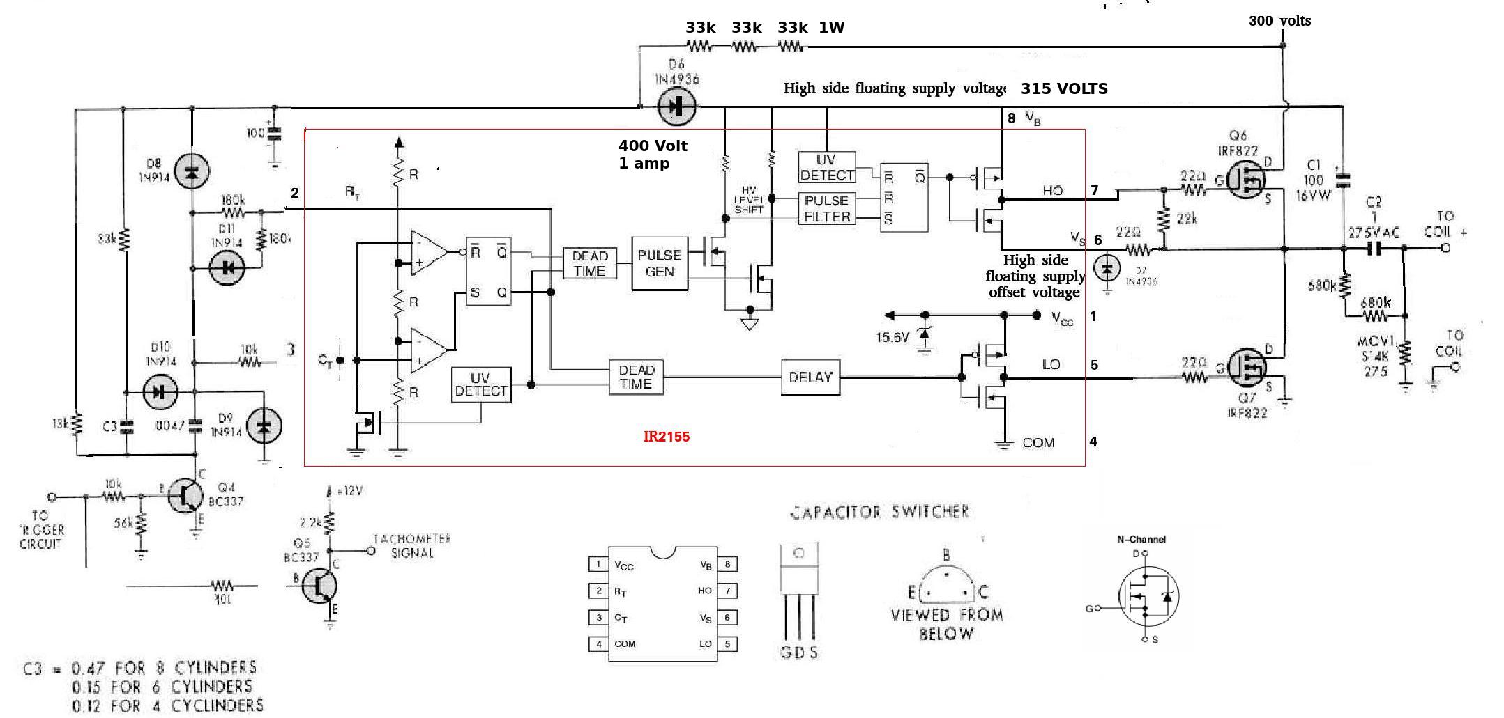
Aden sent me a cap discharge ignition system designed by John Clarke and
published
in Sept 1997 in Silicon Chip mag. An Aussie mag.
It worked for awhile quite well then the push pull HV supply failed as they
are want to do. Something to do with imbalance in the transformers.
One of the very attractive features to me was the high side switch that
prevented the FET from shorting the HV supply when it discharged the
cap through the coil. I addressed that issue in my power supplies by
putting a
series power resister in the line that charges the cap. That has its
drawbacks.
Mostly it affects the overall efficiency. However it is simple and it
works.
So I am working on reproducing that second half of the Aussie
circuit. I have two HV supplies that are working well. One is wall
powered and the
other a 12 volt powered flyback design. High side switches are hard to
design and highly
prone to failure. The IR2155 half bridge driver chip has of necessity a
high side switch.
This chip was used used in the Aussi design and has been replaced by a
more advanced
version. One might ask what is a high side switch? A high side switch is
used between
the load and the the supply. A far more common low side switch is used
between the load
and ground.
All well and good except the Silicon Chip schematic published had an
error that threw me off
for a while. A 1N4936 150 volt zener was depicted as a simple diode. No
text. I added the text.
One of the problems with high side switches is that they require a so
called floating
power supply that is exactly half the voltage of the main supply. John
Clark used a string
of power power resisters from the main supply ending in a the afore
mentioned 150 V zener.
This assumes the main supply is exactly 300 volts. If it is not exactly
300 volts problems will occur.
John tricked the HV supply to turn off when it exceeded 300 volts and
back on when the
voltage dropped below 300 volts. This has myriad unintended consequences
just like
Obama care :) I have developed a feed back circuit on my 12 volt powered
HV supply to regulate
the supply to 300 volts.
I'll let you know how it works.
Paul Lamar
The D6 1n4936 is a fast recovery rectifier. Along with C1 and the
unlabelled 3 resistors are a charge pump ckt to raise the Vb (Vboost)
input 15V above the 300V source. A commonly used ckt with half bridge
drivers because Ho must drive Q6 gate up to 315V to saturate Q6.
Robert.
You are right. I don't know how I got the idea it was a zener.
Did I get that wrong or what? It would have helped if he had
labeled the high side floating supply line with 315 volts.
Makes sense because of C1 being only 16 volts.
Those resisters are 33K one watt.
Maybe I typed the wrong part number into google for the diode.
Does that mean I do not have to regulate the 300 volt supply?
That is good news and encouraging indeed.
It is a real help with you on here Robert. I am glad you are interested
in this stuff. I need all the help I can get.
Are you doing your email with a cell phone?
Do you have a pdf viewer? I sent a pdf of the Silicon Chip
article.
Here is a corrected schematic.
Paul Lamar
The Rotary Engine News Letter. Powered by Linux.
ACRE NL web site.
http://www.rotaryeng.net.
You Tube
http://tinyurl.com/beqqxas.
Copyright 1998-2013 All world wide rights reserved.