Since I am not going to run the 3 rotor TC in a vehicle
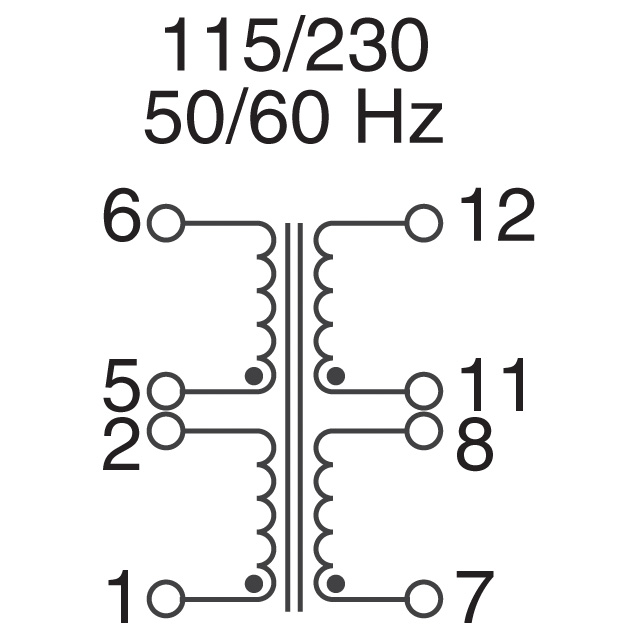
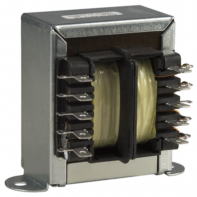
I was thinking of using a cheap 110 volt to 220 volt AC transformer
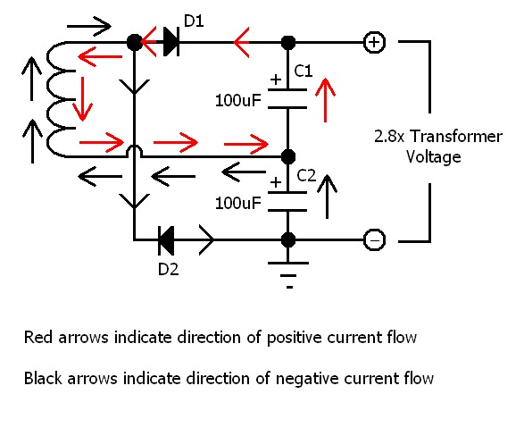
and use a voltage doubler circuit to jack it up
440 volts DC for the capacitor discharge ignition I am designing for the
rotary.
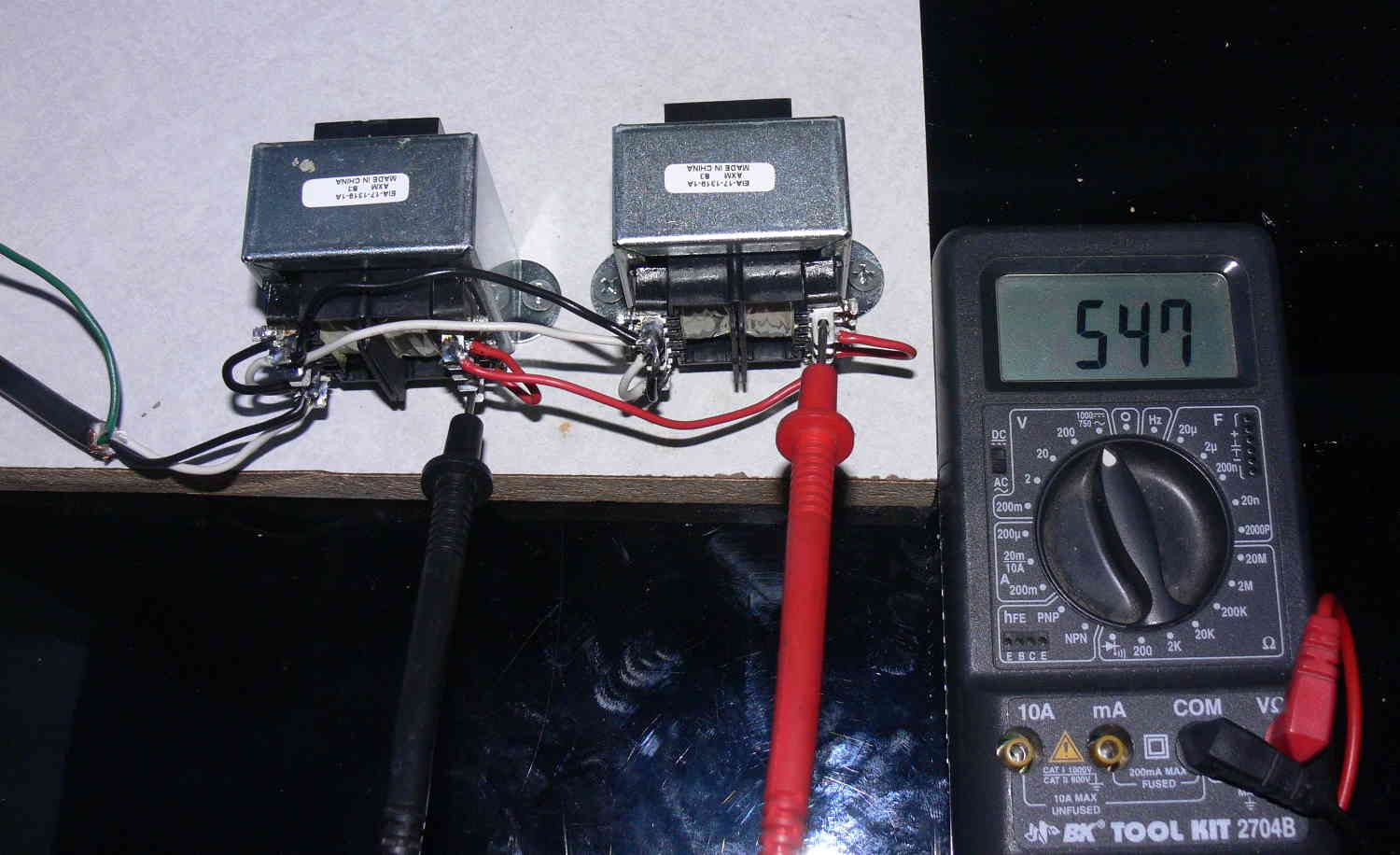
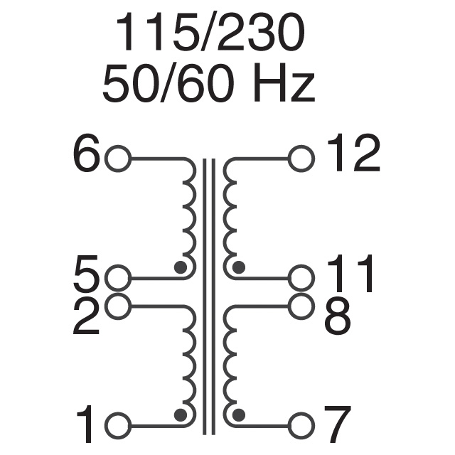
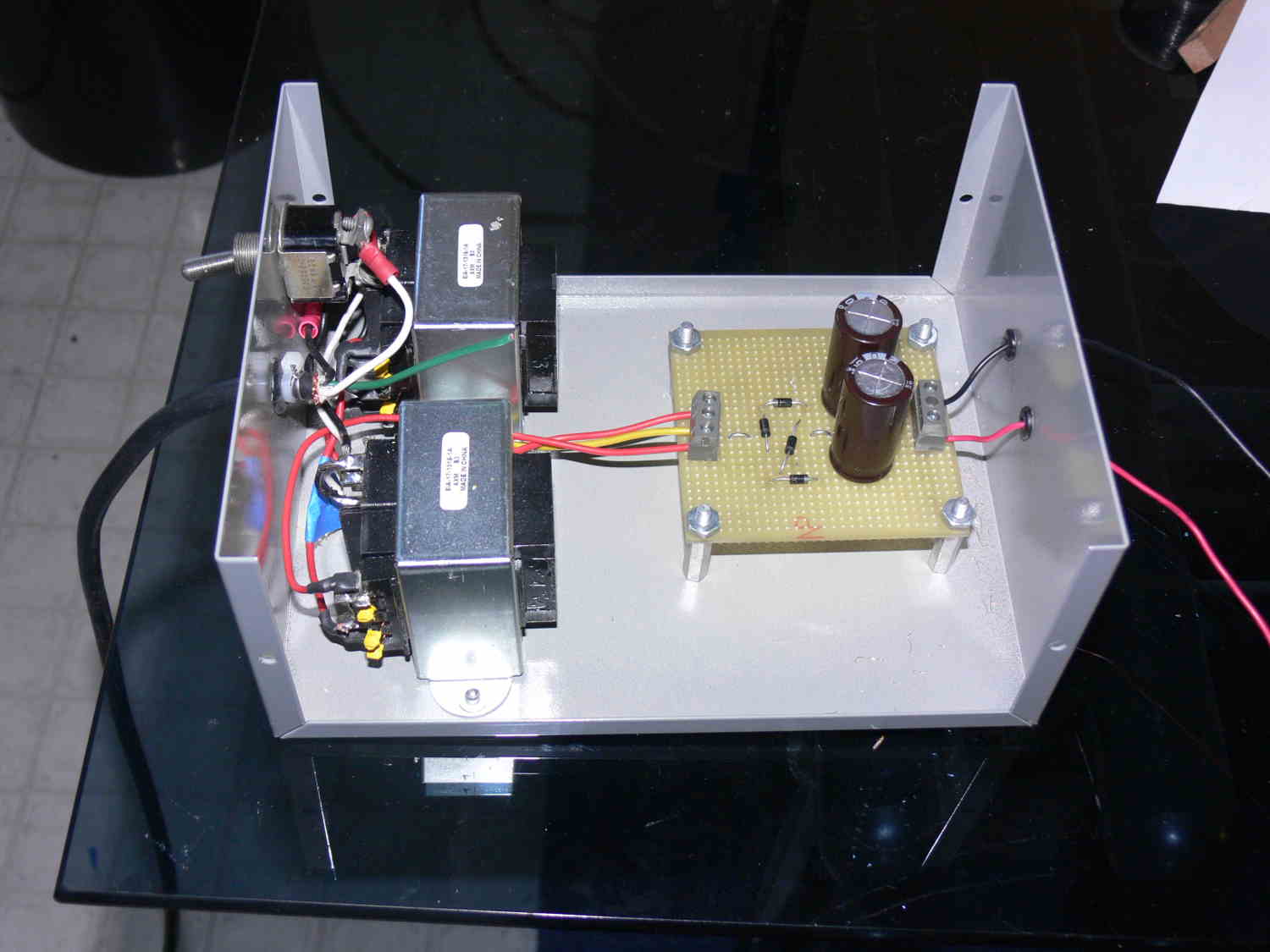
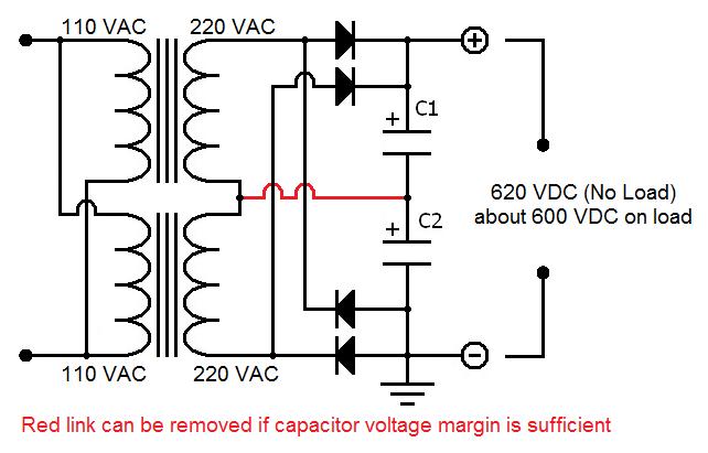
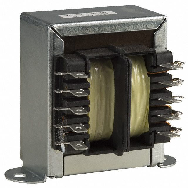
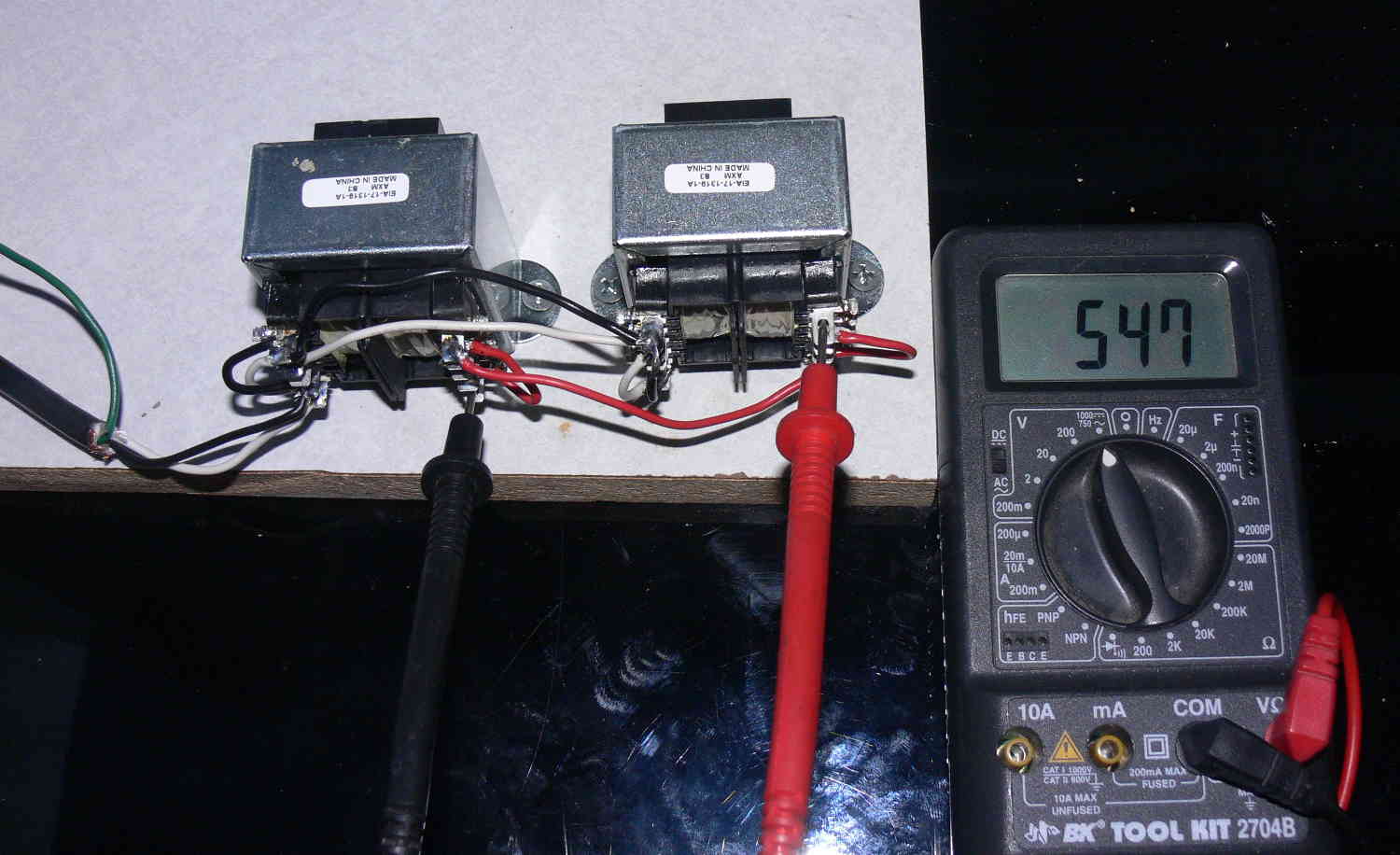
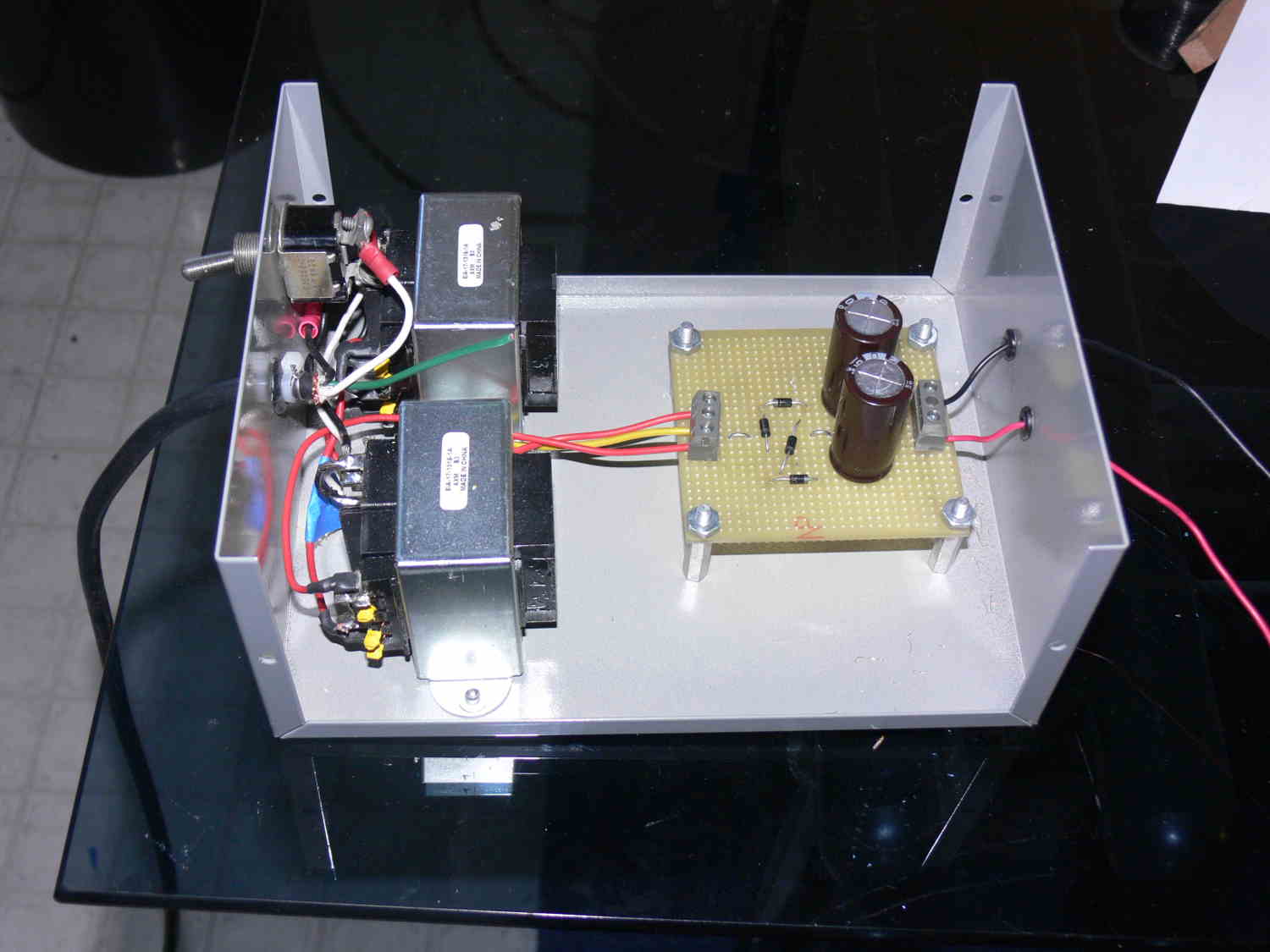
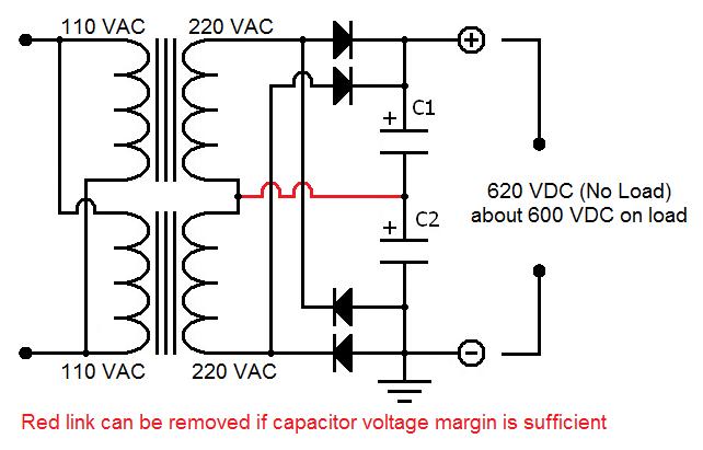
Philippe-Pierre DEJEAN in France had a better idea. Two transformers.
Thanks for suggesting this very simple and robust power supply Philippe.
The 500 volt supply is working great with a 40 watt load.
Next step is dump some 500 volt charged, 2 mF capacitors into a 2nd gen
waste spark coil primary.
One such coil for each rotor.
Paul Lamar
Hi Paul
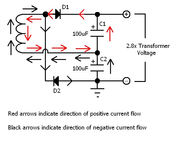
In the wiring diagram I think the cathode of D3 should go to the anode of D1
Bill McDonald
Thanks Bill. I think your right. I am probably losing some DC voltage.
I'll check it tomorrow.
Paul Lamar
The voltage went up to 565 with 4 volts ripple peak to peak.
Here is the corrected diagram.
Paul Lamar
This is the hall effect ignition sensor holder on the nose of the e-shaft.
The green part is 2" wide 1/4 inch thick steel bar bolted to
the large bolts on the side of the front cover normally used
to bolt the air conditioning compressor. Stiffness is everything
when it comes to ignition sensors and steel is three times
stiffer than aluminum.
The screen shot should be printed to the correct size and
used as a pattern to cut the red plastic hall effect sensor holder.
The slots allow timing adjustments. The bolts are 1/4 inch.
I ordered 1/4 inch thick Bakelite from Mcmaster which is strong
and stiff and is a good insulator for the three hall effect wires.
For a 12 by 12 chunk it was $12.
BTW these hall effect sensors do not require motion to work.
They will therefor work down to zero RPM for hand propping.
Paul Lamar
I wanted to try the Aussie John Clarke multi strike ignition on the
turbo 3 rotor
so I am working on that now. It fires twice when the cap is charging and
discharging
no matter what and 4 times at 7500 RPM in 180 degrees of e-shaft rotation.
It also does not short out the HV supply when the cap charge is dumped
into the coil.
MSD ignitions only fire once after 4500 RPM.
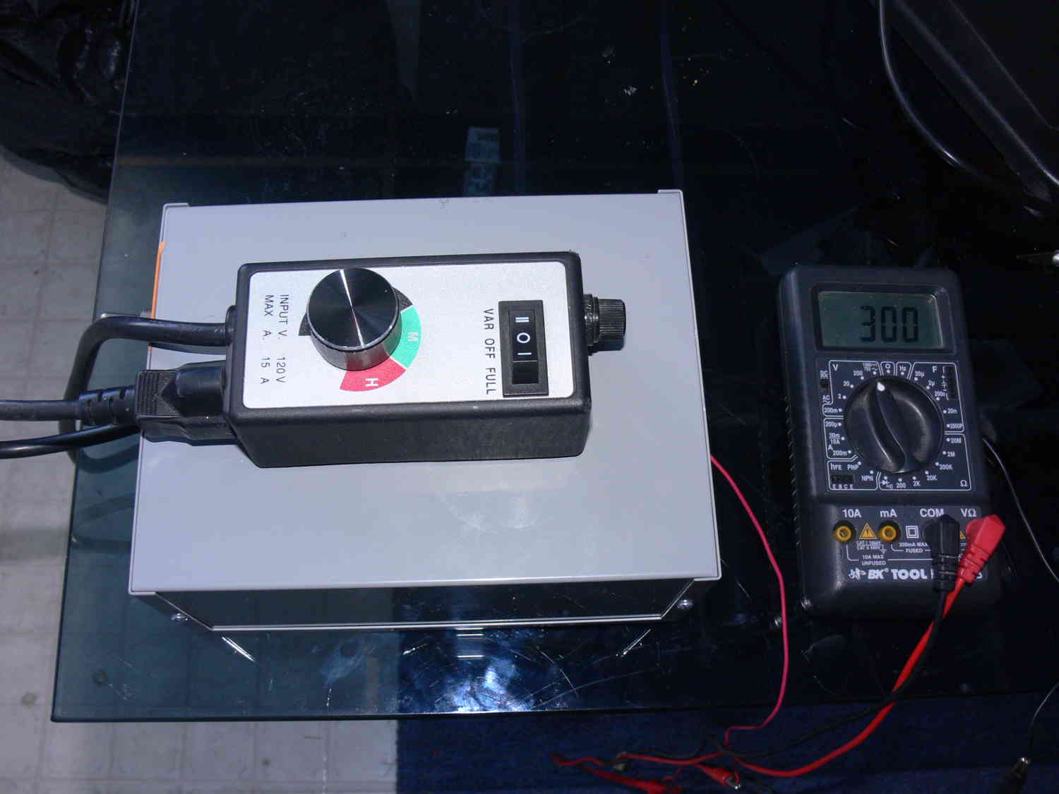
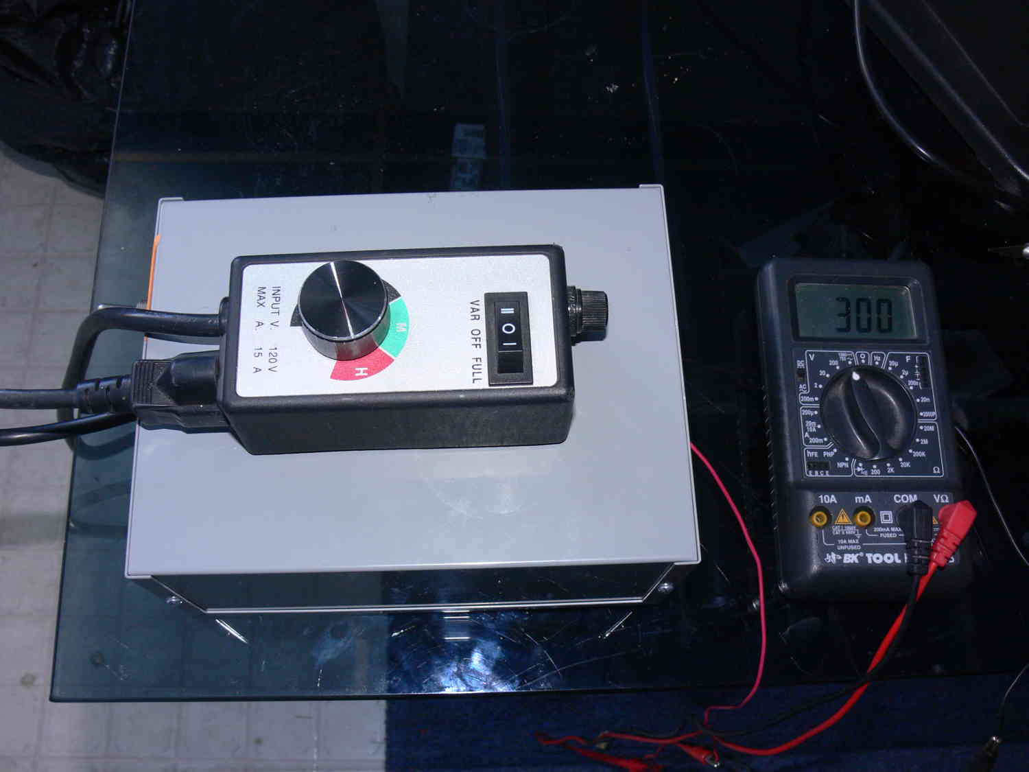
It requires a regulated HV supply of 300 volts. I had this 110 volt
variable speed drill motor control lying around. I plugged the 500
volt supply into it and it is work great to adjust the HV supply
to exactly 300 volts.
So far people have mistakenly adapted piston engine ignitions to the
rotary and that includes
Mazda. Apples and Oranges. The fire moves past the plugs in a rotary and
in 270 degrees
of e-shaft rotation and away from the plugs in the piston engine in 90
degrees of
crank rotation. That is why it is known as a rotating combustion chamber
engine.
So I am going to ignite the mixture every 20 degrees for 180 degrees
of e-shaft rotation. That should burn any unburned hydrocarbons lurking in
the combustion chamber. That will cut emissions and improve the BSFC.
I will test it in the RX8 with OBD II software collecting the air
consumption
and fuel burn data at steady speeds on flat highways.
Paul Lamar
The Rotary Engine News Letter. Powered by Linux.
ACRE NL web site.
http://www.rotaryeng.net.
You Tube
http://tinyurl.com/beqqxas.
Copyright 1998-2013 All world wide rights reserved.