Hi Paul, Do you have any more info on Tracy's box, like the shaft and
internals, I can't figure out where the thrust goes etc. The box is
very chunky, I would say overkill somewhat. Also I can't see any oil
supply, in or out. You wouldn't have to saw off the flange, I would do
my box and then remove it from the pattern before casting others. From
the side view it looks like the prop shaft is one piece, is this right
? Also, is the box intended to be bolted up to a plate or a bell
housing. Chris.
Tracy used a cut down GM pick up truck rear axle and ball bearing.
The bearing was retained by a pressed on collar with several tons of
force.
Tracy fed the box with oil from the engine. So too the Ross but the Ross
had all needle bearing so it required less oil.
Very heavy at 9 pounds, I would not do it that way.
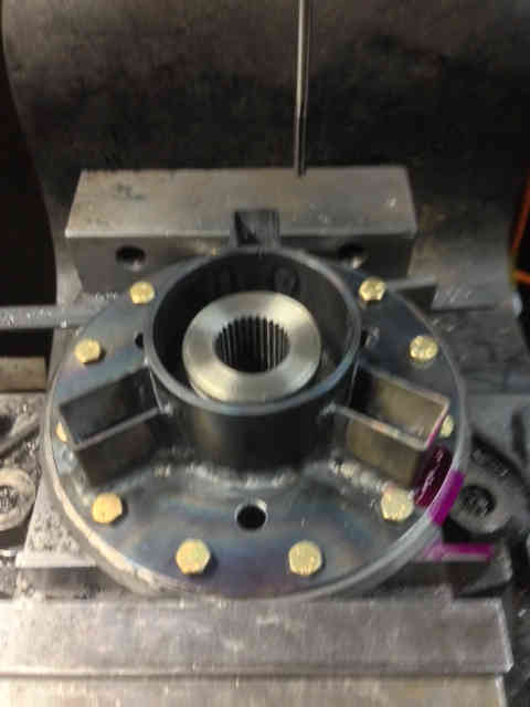
I would use a hollow shaft like the Ross with a separate prop flange.
No forging required. The flange would be retained by
special set screws called "Extended Point" . A relatively new idea
and much stronger than pins that go all the way trough the walls of the
shaft (which is what Ross used for years) or splines and much less cost.
Easy to machine with a rotary table.
About a 2 inch OD steel tube with a .190 wall is about right.
Just like the Ross box. That is about the largest needle bearing you
can buy.
Use about eight or ten of these .25 inch screws and they are almost as
strong
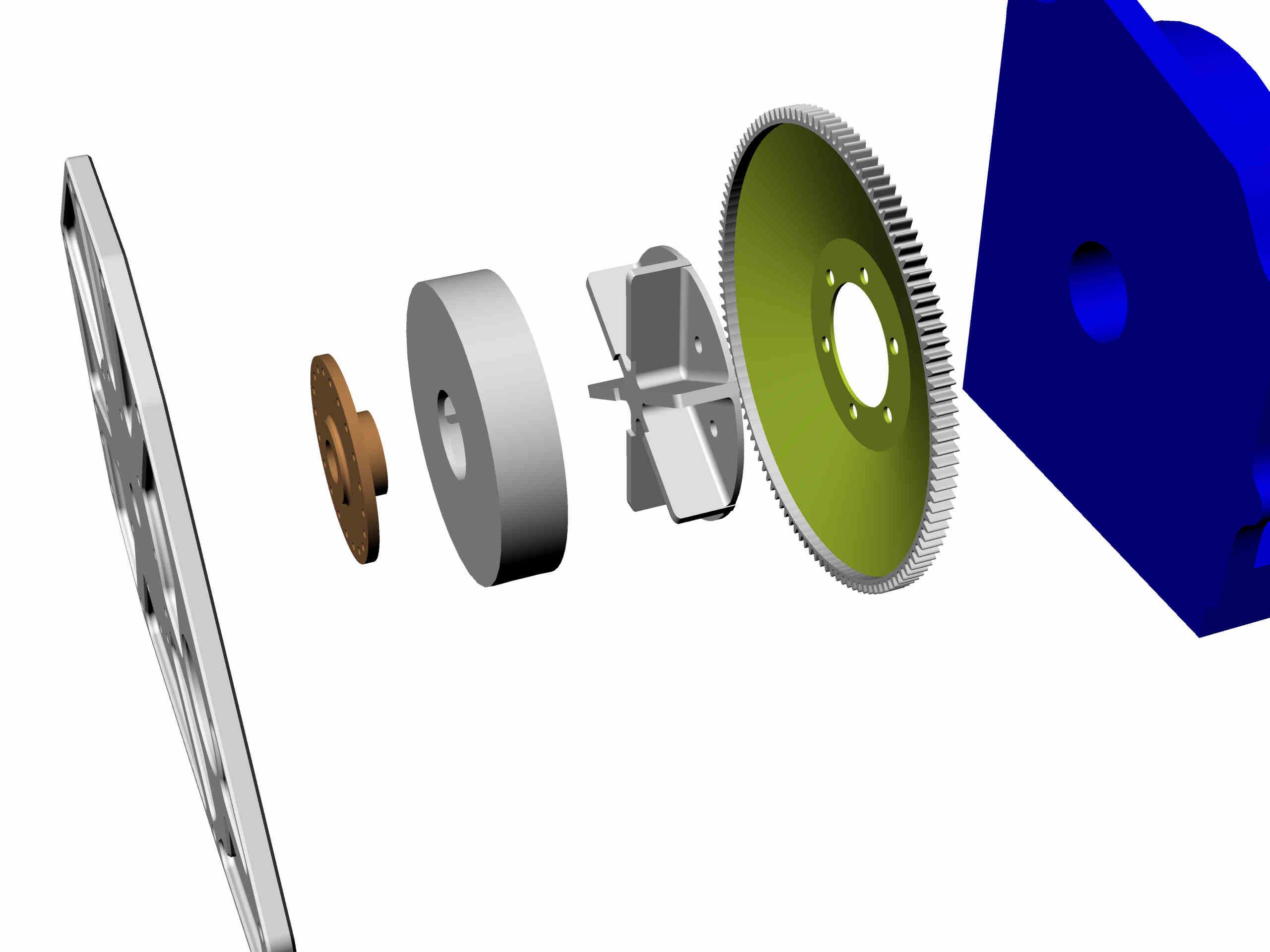
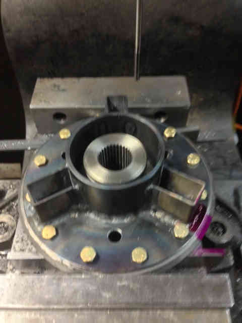
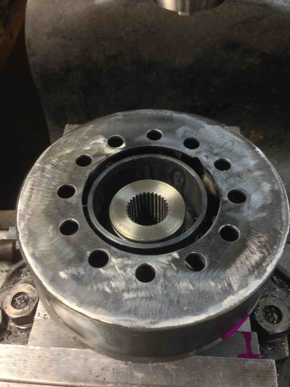
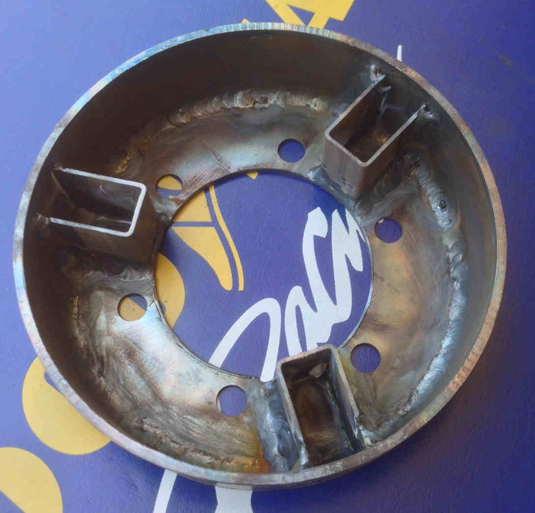
as a one piece shaft and flange. Here are some pictures.
Do you use a dwg program Chris? If not I suggest getting Rhino.
It will save you money in the long run.
Paul Lamar
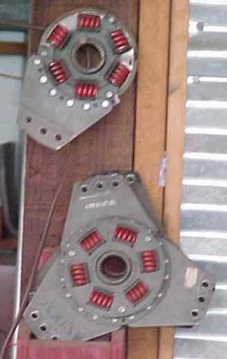
Paul, Refresh my memory, What was the problem with the springs in the
original flex plate? I always had the impression that springs would
absorb the torsional pulses and return the energy when pulse subsided
whereas rubber dampers would dissipate the torque pulse as heat?
Erik
No damping. Ken Welter destroyed a couple of them.
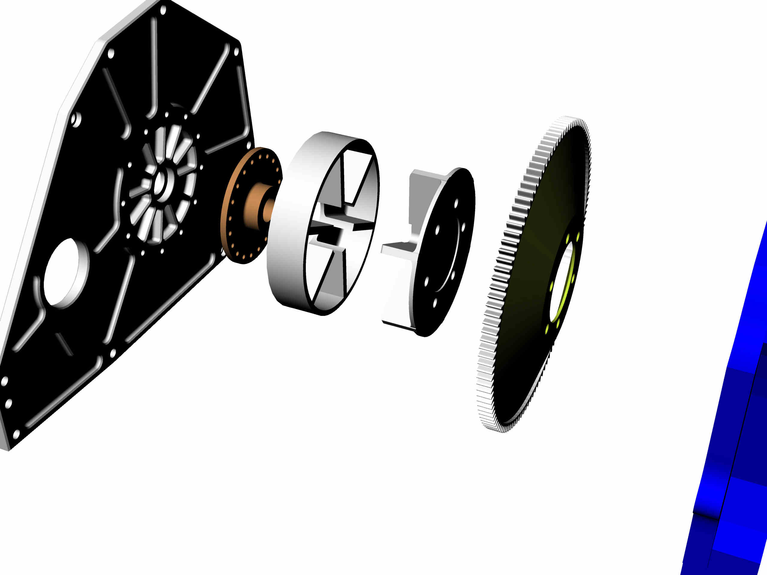
Our new silicon rubber coupling is the way to go.
Chris, you will need something like this.
Paul Lamar