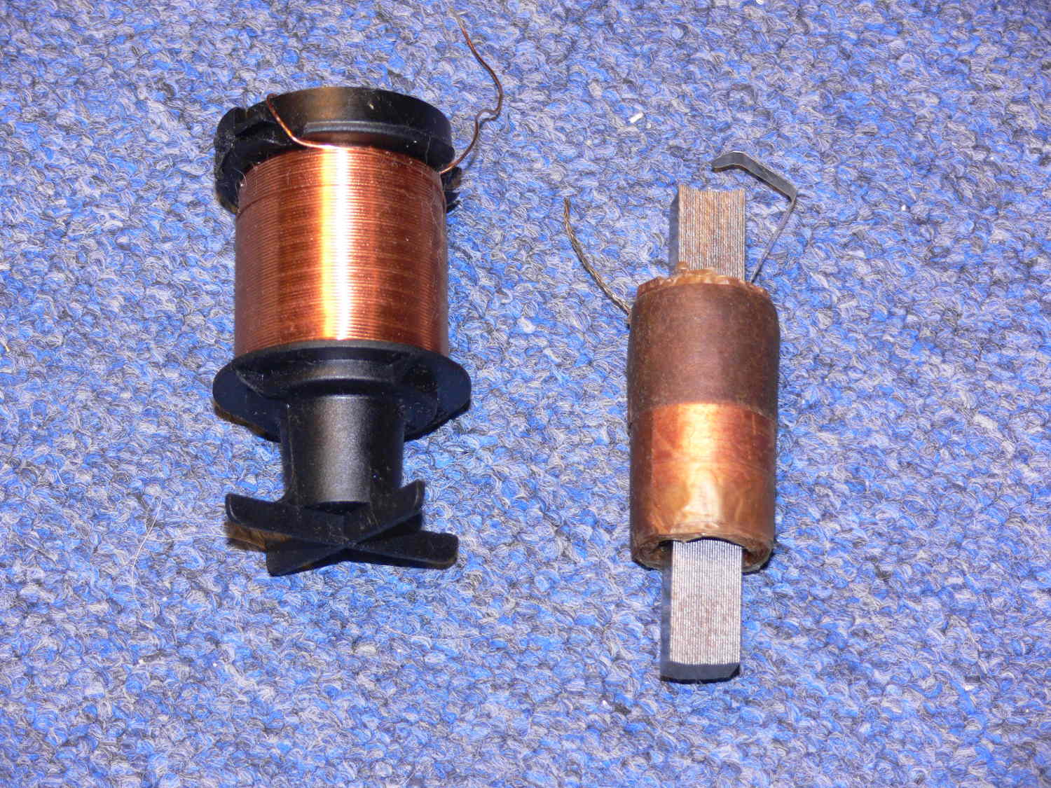
flat strap is ground. I did not unwinds the secondary of the old oil
filled coil so I don't know how many turns.
correction. After reading your message again I guess you got a spark
from the merc coil. Are you shocking the primary of the merc coil?
Or are you using a cap to couple the flyback coil to the merc coil?
-----------------------
Is this the pictures you are referring to?
If I wind the primary on the outside of the secondary 4 or 6 turns will
have higher
dc resistance. The length of the primary wires in the wurth are lonly
about 10 inches long.
They were about 6 turns in the Wurth.
DID YOU GET A SPARK?
If yes what did you use for a high voltage secondary?
Please send me a picture of what you made.
If you use push pull don't you need a float voltage?
How do you get a push pull to fire once?
Paul
On 12/14/2013 12:00 PM, Robert LeClercq wrote:
Interesting; placement of the pri is usually on the inside for most
xfmrs I ever disected. In the case of a hi V sec the pri would not be
placed close to the hi V windings. So which of the sec wires was at
gnd and which to the plug? If that flat strap was the gnd then the
hi V would be on the outermost windings. In that case I would place
the pri as in the first pic, which must have been the original
placement. Now about that 9K res. What was the original turns ratio?
It would take a lot of small gauge wire to make 9K; so my guess is
there is a suppresion res somewhere in there.
Last nite I thought a lot about your flyback idea. I dug up a some app
notes and calculated a push/pull version flyback xfmr. It takes a
large core, powdered iron for lo permeability. Wound it up with 2 pri
and a sec. I Just tested it this morn and damned if it didn't work. I
also used the resonant sec as my earlier design and the Merc coil.
About .1A pk sine wave of plug current; 10A pk sine in the pri and 50V
pk sine on the pri. My half bridge ckt put higher V on the pri with
about the same output levels.
On Saturday, December 14, 2013 10:57 AM, rotaryeng
<rotaryeng@earthlink.net> wrote:
This is the guts of the old oil filled coil.
The secondary is 1.2 OD 2.1 inches long.
The center hole is .7 inches ID.
The resistance is 9.5K
the iron core strips are .4 by .5 inches.
I will rewind the primary with 4 twisted wires about 5 turns each
winding.
Each primary winding was 5 wires twisted together each wire .019
(19 thousands) in diameter 8.5 inches long. 25 AWG.
There are 4 of these windings hooked in parallel.
Basically a copy of the Wurth primary.
Where is the best place to put this? At the bottom
of the secondary or wound around the out side the
the secondary?
Paul