All you guys in Oz & Nz got to get a Jan 14 back issue as there is an
article on how to build an EFI with a low cost Arduino micro
computer. This will be a good education in EFI's. I ordered a copy
for me shipped to the US for $15 Oz
Silicon Chip mag is a great Oz publication for buying and learning
electronics.
http://siliconchip.com.au/
What works on one cylinder works on one rotor. It's cheap enough to
dup it for the second rotor.
Don't mess around. They will be sold out of Jan back issues shortly.
Paul Lamar
I strongly recommend Arduino kit. I made some by Ebay's chinese circuit.
mostly charging battery and drill and soldering. but as going study
harder. most circuit already on Ebay or any hardware store. only left
thing is controller.
Arduino is very very cheap and most of all it's programming language and
IDE is most valuable. just plug in via USB and install IDE( programming
software) you can programming micro computer . and there is already so
many example at IDE,
( IDE is just same as word processor, it's programmer's word processor )
there is so many tutorial about this.. I just pick this. but you can
search all about it.
http://www.youtube.com/watch?v=E6KwXYmMiak
<http://www.youtube.com/watch?v=E6KwXYmMiak>
<
http://www.youtube.com/watch?v=E6KwXYmMiak
<http://www.youtube.com/watch?v=E6KwXYmMiak>>
making 3D printer or CNC also very easy. there is already part and
firmware there. and we can use this as almost everything. we can use it
monitoring voltage at sensor so on.
http://www.youtube.com/watch?v=85LvW1QDLLw
<http://www.youtube.com/watch?v=85LvW1QDLLw>
<
http://www.youtube.com/watch?v=85LvW1QDLLw
<http://www.youtube.com/watch?v=85LvW1QDLLw>>
http://www.youtube.com/watch?v=gDFeXYWxQ_Y
<http://www.youtube.com/watch?v=gDFeXYWxQ_Y>
<
http://www.youtube.com/watch?v=gDFeXYWxQ_Y
<http://www.youtube.com/watch?v=gDFeXYWxQ_Y>>
IT's key is easy to programming. that's the key and there is already
many tutorials and datas. I recommend it as software engineer expert.
P_Bear.
Using the Arduino IDE has some drawbacks- as you add more
digitalWrite commands and digitalRead commands, it slows down
considerably. The problem isn't the chip, its the Arduino IDE. The
Arduino.h file that includes the functions that allow the digitalWrite,
digitalRead, analogWrite and analogRead functions require the compiler
to write a lot of non-optimized code. For example, to enable
digitalWrite on pin A1, the compiler has to write 8 separate lines of
code- one for each bit for each of the available pins. Same for the
other commands. This ends up taking a lot of the processor power for
unnecessary commands.
The only way to make the Arduino work for an EFI would be to write
the code in C or C++ and manage the bits individually. While the
Arduino IDE is simple enough for beginners, it is not suitable for a
really high end high speed critical system.
There is another board made by Texas Instruments called Hercules
that is much more suitable for an EFI- it has a built in watchdog timer
as well as built in self monitoring provisions. The board is marketed
for "safety critical" applications, which an aircraft EFI would be.
I wrote the code for an Arduino Mega 2560 that monitored the
potentiometers for 4 linear actuators, would read the pots and control
the pwm for 6 channels of LED lights, it read the temps inside and out
and monitored the output of an electric heater for safety purposes. The
system ran slowly enough that it would miss the stop points for the
actuators causing the actuator to "hunt" for a bit before stopping at
its intended location. Once I identified the problem, I was able to use
a different IDE to write the code at the bit level and make it work. The
problem turned out to be the time required for the system to read and
write to all the pins, and the time lost to the ADC.
If you want to see for yourself, the Arduino code for a lawnmower
EFI system is on the internet, as well as a Youtube video. Download the
code into the Arduino IDE, then compile it into assembly. As you go
through the code you will see what I mean.
I have been working on and testing bits and pieces of a similar
system for a while now and my conclusions are that the best system would
be built on the Freescale S912 series chip or an ARM 7 or 9. The
freescale chip has a second chip on the board known as Xgate that has a
singular purpose- to read sensors and gather information. This frees up
the main processor which is many times faster than the Atmel in the
Arduino to do nothing but calculate and bit bang the injectors and other
necessary items for the EFI.
Kevin Alderman
Kevin what about multiple Arduinos one for each injector and one
for the display?
The Motec is $3000.
If you want a real powerful ARM I have just the board for you :)
You can have it for what I paid for it in a day or so. About $200
I just don't have time to work on it. I am focused like a laser on
the ignition :)
http://www.mikroe.com/
Paul Lamar
Its not so much the Arduino, it is the Arduino IDE. The arduino guys
went to a lot of trouble to make an IDE that was easy to use, but this
has drawbacks. When you call digitalWrite, the compiler literally has to
write 10 to 12 lines of code to make that work- and it does it for each
pin.
How it works in a nutshell and kind of generally. If you look at the
Mega pinout for the chip itself, you will see things like PA0, PB1, etc.
The actual layout goes like PA0 through PA7, PB0 thorugh PB7, etc. Each
pin is part of a group of 8 bits 0 - 7. What the compiler does when you
call digitalWrite(A8), it will use the IDE header file to find A*, which
is PC0. It will have to write to that bit, while not changing any of the
other PC bits- so it will call the code PORTC_0 0b = 10000000, where
port PC0, aka A8 is given a bit of 1, and the others are given a 0. This
sets that particular pin to high, and the others to low. Now, you might
not want A9 to be low, so it will stick another line under it that looks
like PORTC_1 0b != 00111111, which will in effect invert the other bits
to the opposite of what they are. So, since somewhere in the program A9
is HIGH, the program has to flip bit one and 2 of port C to high and
then flip the remainder to LOW, and keep checking each bit and comparing
to what the program needed before it got here. This takes up a lot of
processor time and makes it slow if you have any complexity at all.
If you learned C or C++, you would be able to call each port (pin) with
an individual bit, and not bother the rest unless you needed to. This is
called bit banging- changing a single bit high or low to turn something
on or off repeatedly.
There are other issues, but the problems are mostly related to the
Arduino IDE and its inefficient compilation so that people don't have to
learn C. And stay away from the delay function if you can- it literally
stops the program. I use delay only if I want to stop the program- like
if I want to move the actuator with a button press. The chip will read
the button press so fast that no matter how fast you are, it will read
multiple presses. So, if the button is pressed, I use delay for 20ms do
"debounce" it. I also use code that says if the associated pin is HIGH
for more than once in a period- 200 ms works well- then it reads as one
press. I also successfully used code that said that until the flaps were
at position 1, you cant select position 2, which prevents one long press
giving full flaps at the turn from base to final when I only want one
notch of flaps.
This is actually used to control the flaps in my Wheeler (along with the
lights, etc.) One press lowers the flaps to 10 degrees, but only if the
airspeed is lower than 110 knots. 20 degrees if airspeed is less than
90. 30 degrees if airspeed is less than 80. In the event of a go around,
i.e. full throttle, and airspeed above the limits, the flaps come up one
notch at a time. Trying to make my plane idiot proof. It works quite
well at this point, and is built on an Arduino Mega 2560. I can also
disable the automatic flap part and manually control the actuator with a
single switch on the panel. I like backups.
I dont like the idea of a 2 inch hole in my firewall where noise and
exhaust can come in, so I opted for an electric heater. I use a digital
temp probe that will shut off power to the heater if the output temp
exceeds 120 degrees, which means the fan has stopped. You can use this
approach to monitor basically anything in the aircraft. However-
displaying the information drastically slows down the processor. If I
wanted to use the Mega to monitor and display a lot of parameters, I
would use a board just for the flaps, and another board for the other so
that the displayed info doesnt slow it down too much.
One more thing that significantly slows down the arduino is
serial.Print. speed killer.
If you want to see it first hand, get an LCD shield. The lcd.print is
faster than serial.Print. Load some code in, and watch the update speed
of the lcd. 3 or 4 serial.Print lines and you will be able to see the
blink of the lcd update, indicating a slow down of the processor.
For critical systems, I would opt for an RTOS, real time operating
system. Basically this OS gives a time and priority to each function or
almost line of code. If a sensor is having an issue, the program wont
get stuck there but use a default value and skip it after a programmed
amount of time. This approach is used in fly by wire and FADEC systems.
Now to finally answer the question- yes you could use multiple boards
like one for spark, one for fuel etc. But you would lose the ability to
fine tune the whole system at one time. I did test using one board for
the strobes, one for flaps, etc. and it works. Some of the 16mhz tiny
pro boards are on ebay for like $3, and these work well for little
programs.
Kevin Alderman
I got it Kevin.
What about my ARM board? Mikroe is a great outfit. They do everything
they say
they are going to do.
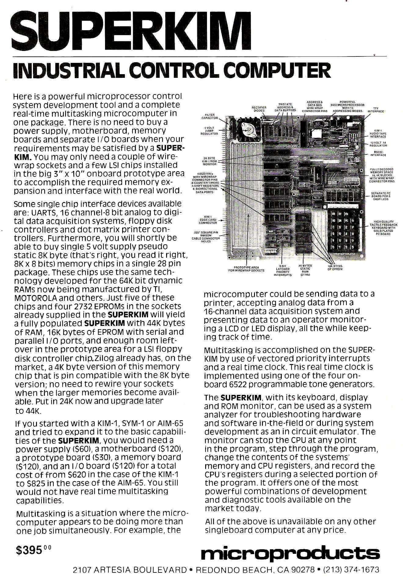
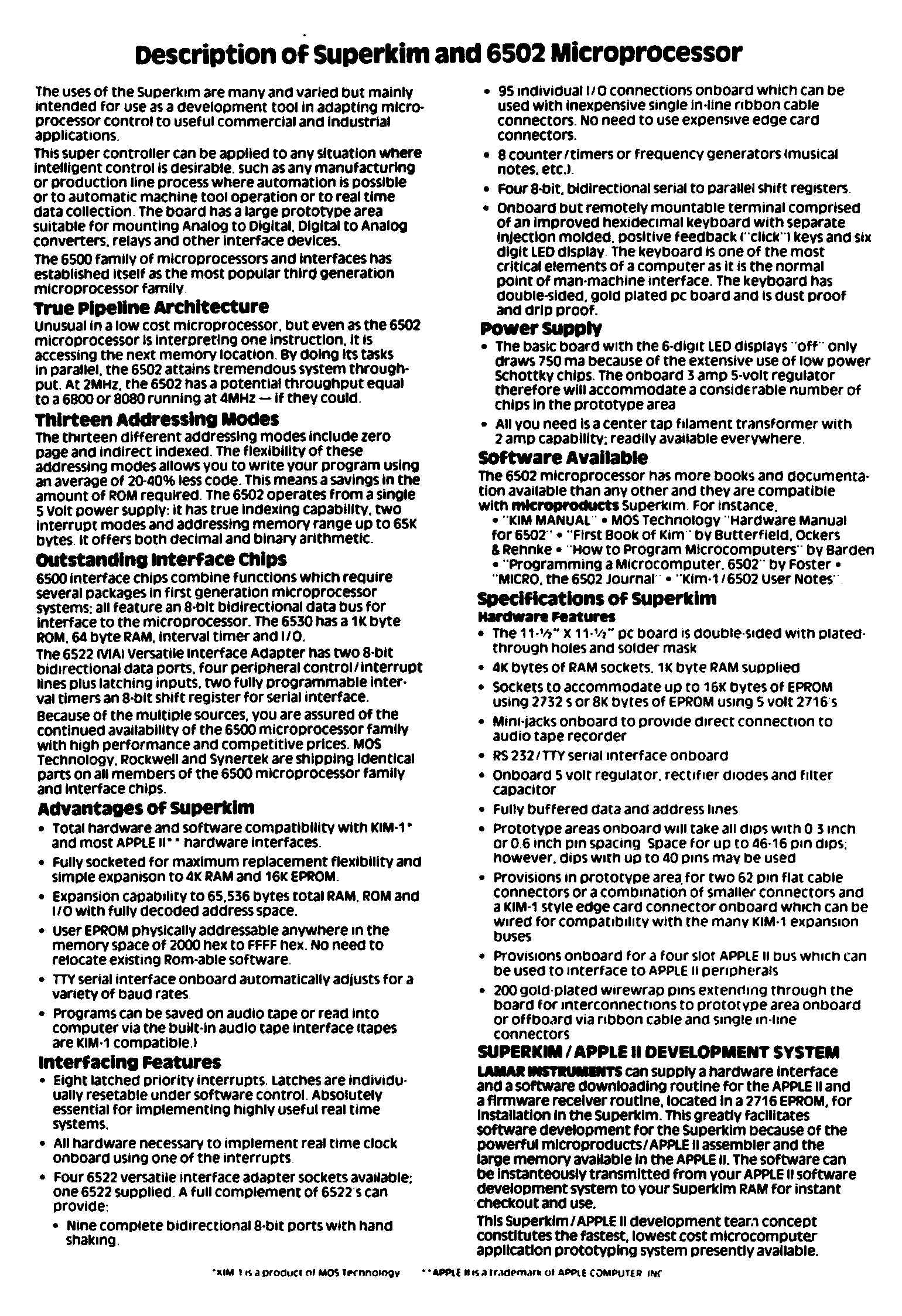
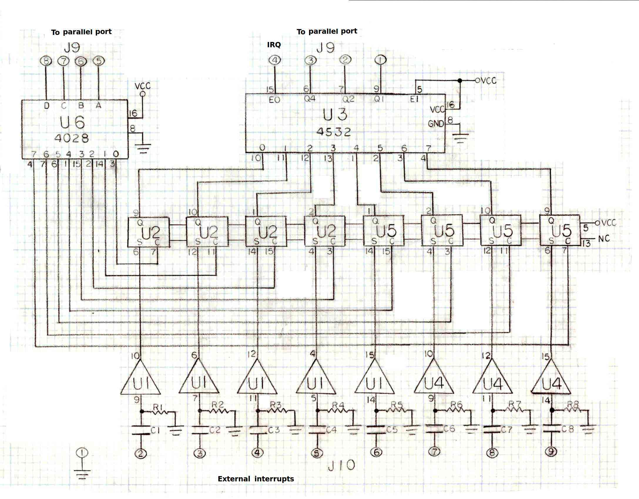
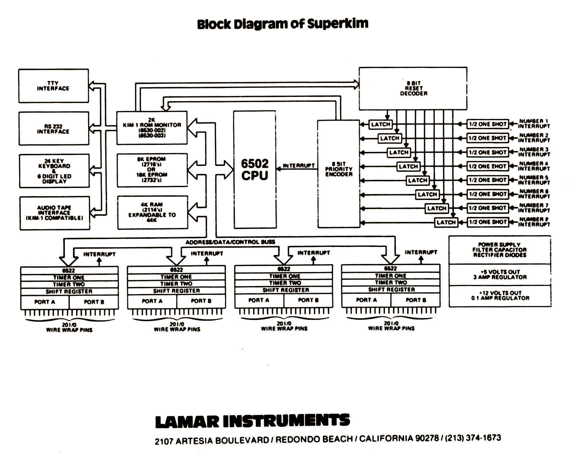
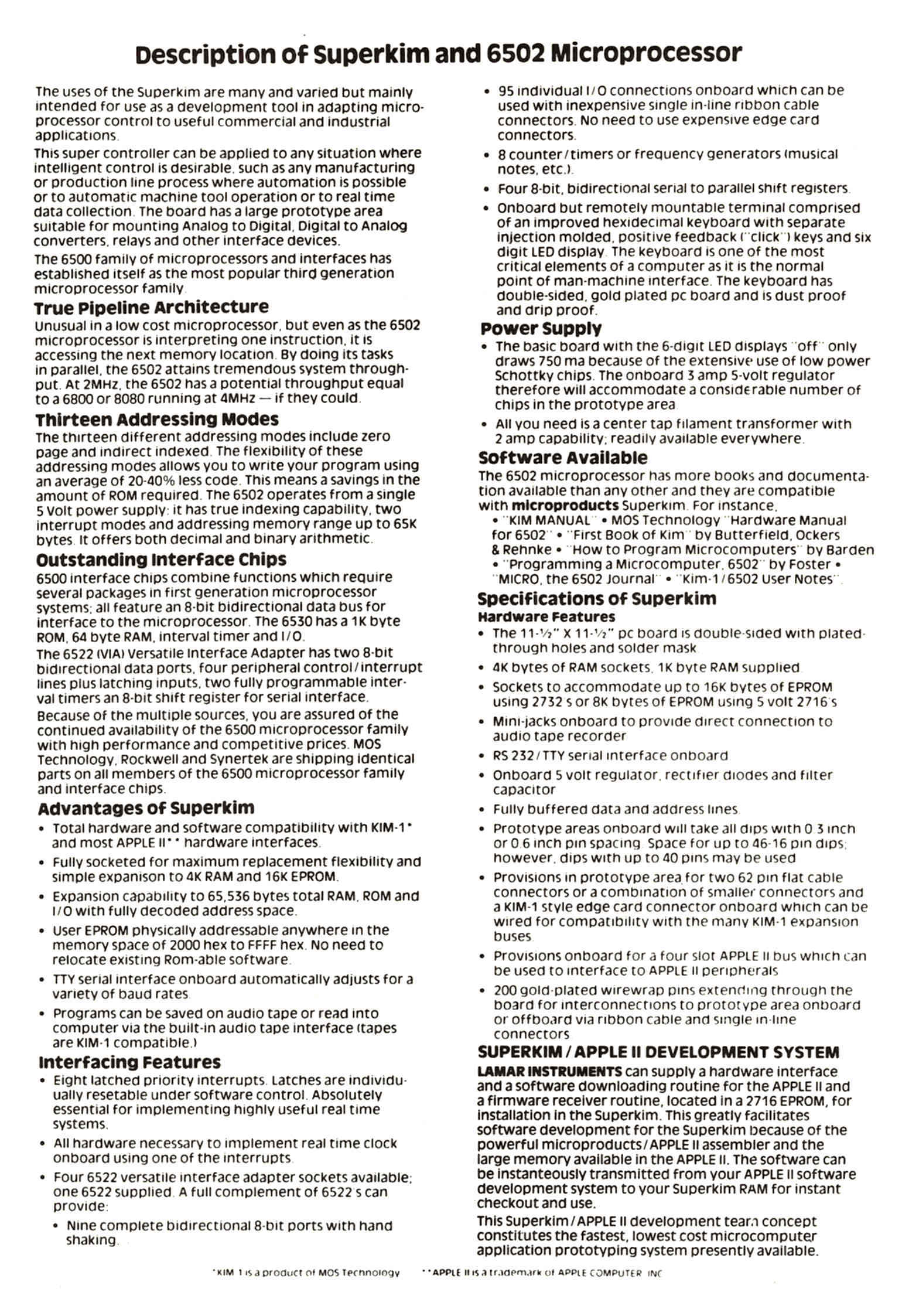
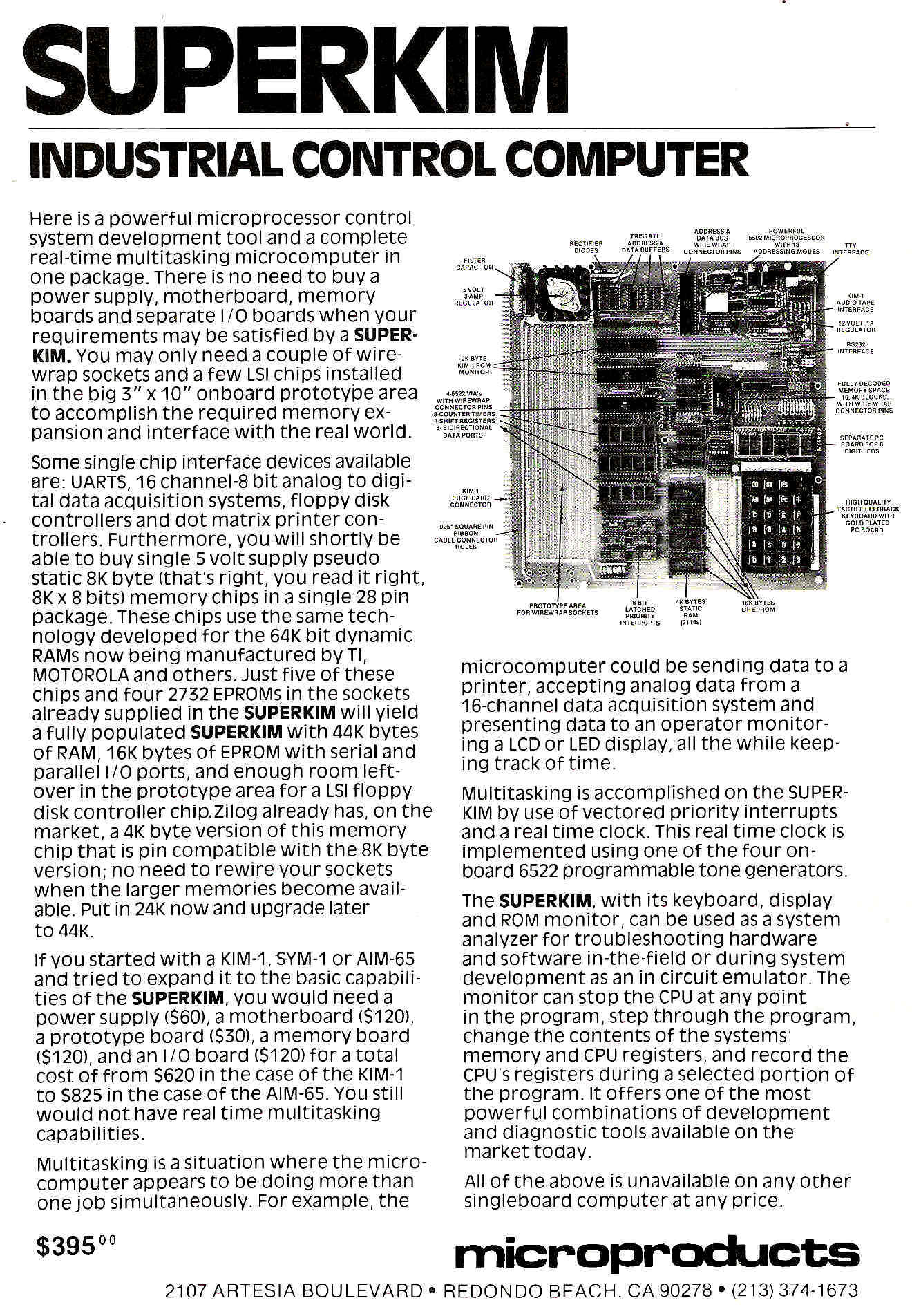
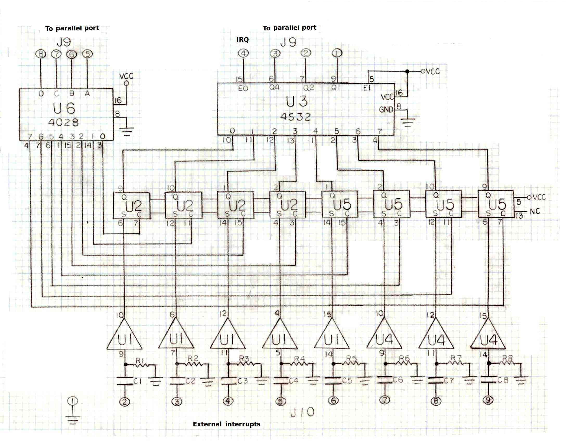
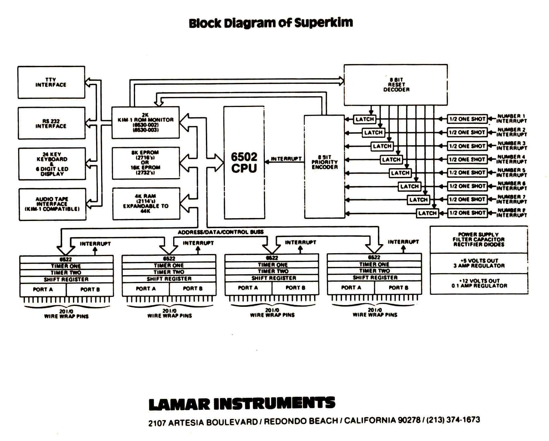
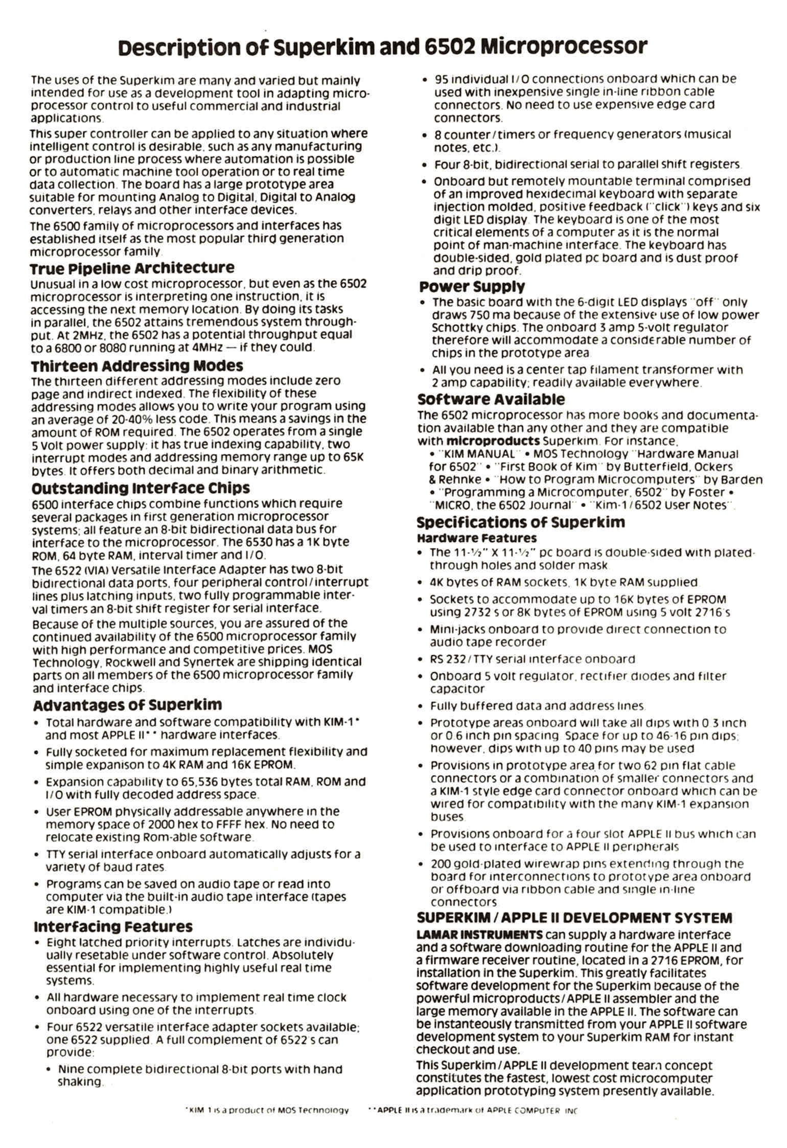
You want real time check out my SuperKim I built in 1975 :)
Paul Lamar
The Rotary Engine News Letter. Powered by Linux.
ACRE NL web site.
http://www.rotaryeng.net.
You Tube
http://tinyurl.com/beqqxas.
Copyright 1998-2013 All world wide rights reserved.