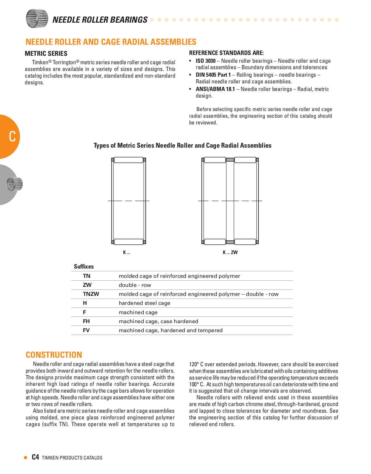
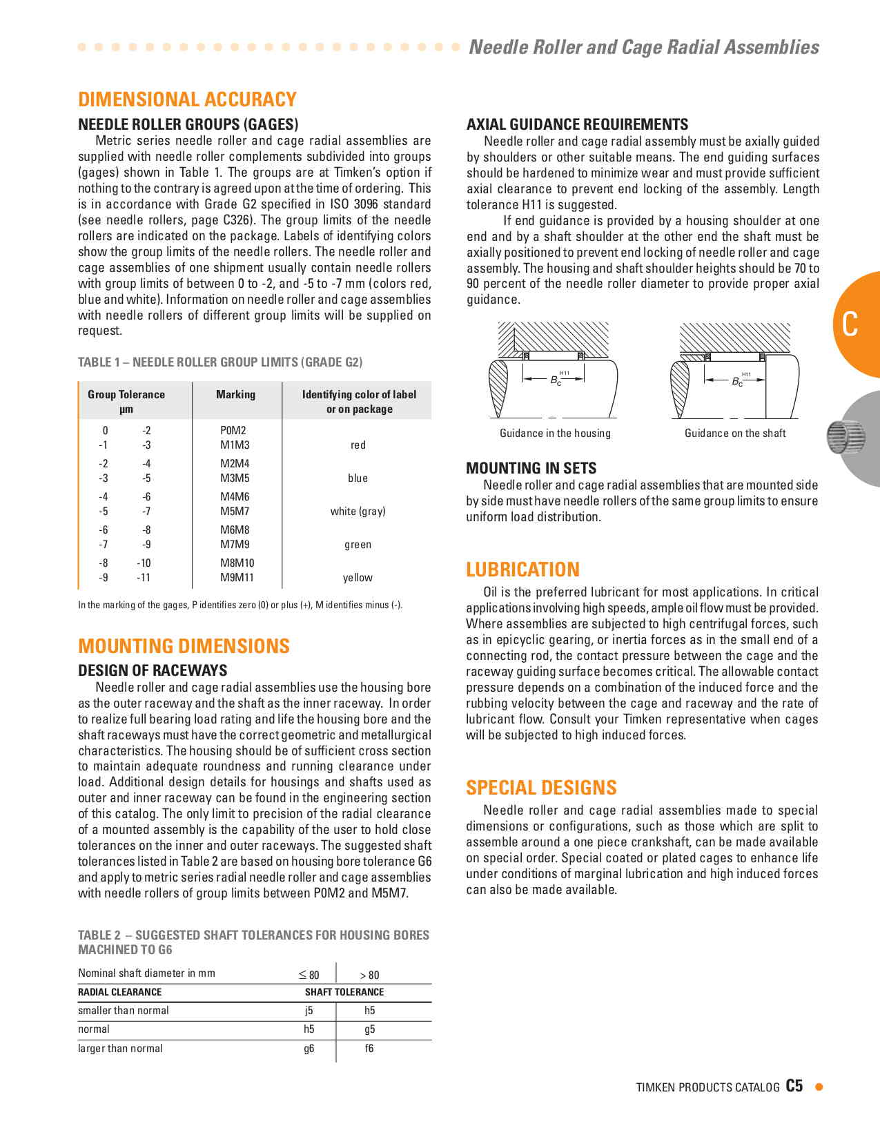
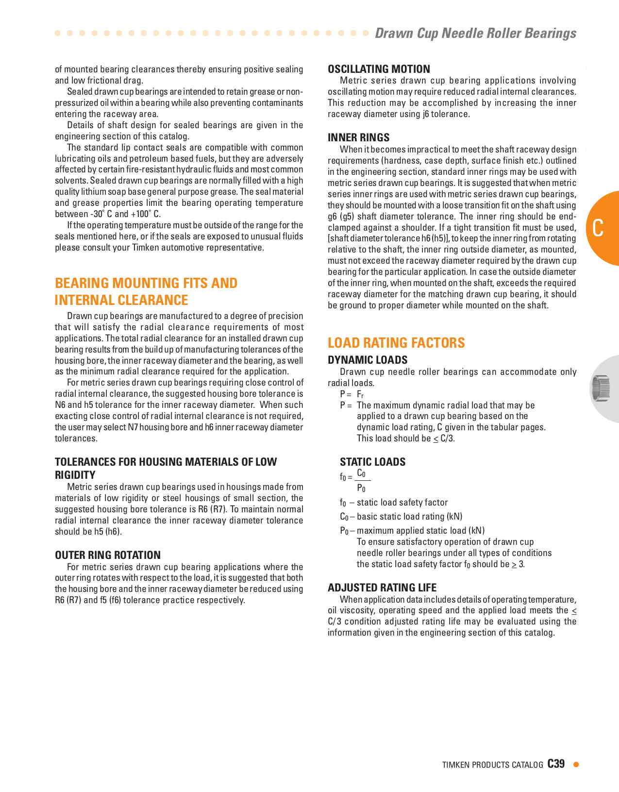
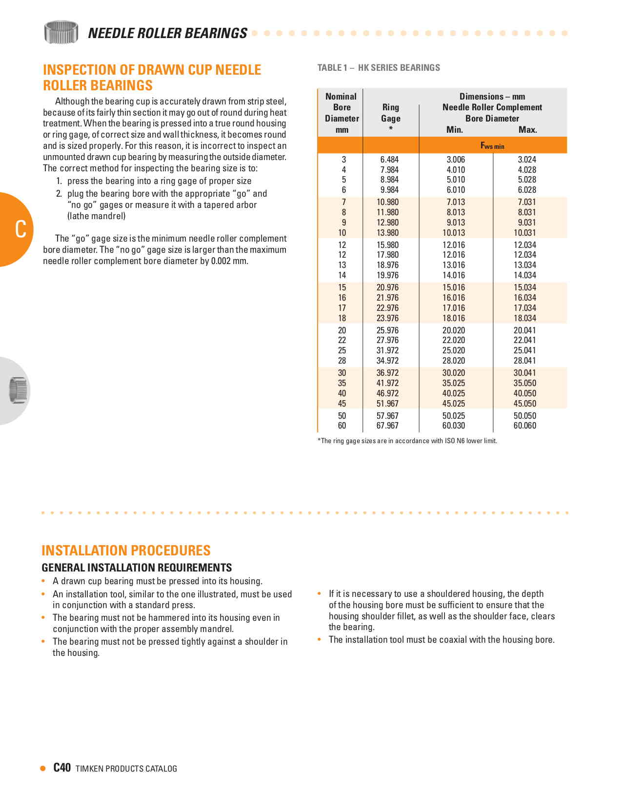
Use extended point 3/8-24 set screws 1/2 inch long. Drill the flange
and shaft together on a rotary table six places with 1/4 inch drill.
12 places if you want to be conservative.
Then use a tap drill on the flange and tap.
This is much stronger than a spline or two 3/8th pins used by Ross.
Easier to get off for inspecting the gear box.
Note that the extended point set screws do not go all the way through
the 1/4 wall prop shaft. Only to about .1 inch deep. This retains a
lot of the prop shaft strength in this area. This is stronger than
a spline.
With a P-port and a 3.12 to one gear ratio prop torque is 200 X 3.12
or 625 foot pounds. Therefor the shear load on the set screws is
only about 100 pounds each. 200 pounds peak each depending on the
rubber bushing coupling the engine to the sun gear. More if prop
thrust is added in. Use 12 of these screws to be conservative.
Use the SAE #3 flange dimensions for wood and composite props.
If you go with a Warp Drive/Sensenich style ground adjustably SAE #1
flange can be used.
For the P-port rotary you will need four Sensenich carbon blades.
Paul
Paul, Good idea actually, finally understand what you are on about
and simple. What is the prop flange made of, alloy or steel?? Feel
steel would be better with the retaining screws or am I dreaming as
usual?? Neil.
4340 heat treated to rockwell 60 or so.
Paul Lamar
Hi Paul, Where do I find .250 wall 4340 X 2" tube ? Chris.
That is for the flange. 4340 bar stock. Have them cut off a 2 inch
junk out of 6 inches OD. I think your adjustable pitch prop can use
an SAE #1 flange.
The 4130 tubing is for the prop shaft.
You can have it dropped ship to me and I will mail it to NZ or have
your airline pilot friend pick it up at SFO.
Paul Lamar
Paul, The tube that is part of the prop flange will have to be long
enough to extend into the housing as it will have to be what the
seal actually runs on. This will make repair simple in the future
should the seal surface wear. Then I feel that we should have two
small keyways to locate the prop flange so that replacing the flange
at any time is a simple "line up the key way" and tap on. That way
all the holes have to line up every time. Then we need a ledge to
insert a plug against in the prop shaft so that a puller has
something to work on when pulling the prop flange off at any time as
it will almost weld on over time and very difficult to remove unless
a puller can be used. Again just a detail, but very important to
facilitate dismantling down the track. I am paranoid about ease of
maintenance. All my life I have had to maintain machinery that was
never allowed to come apart. Neil.
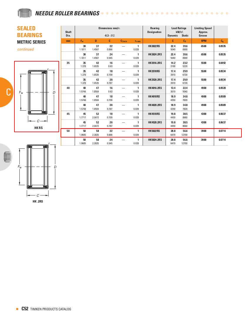
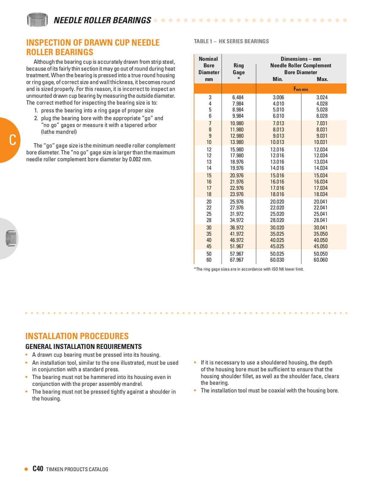
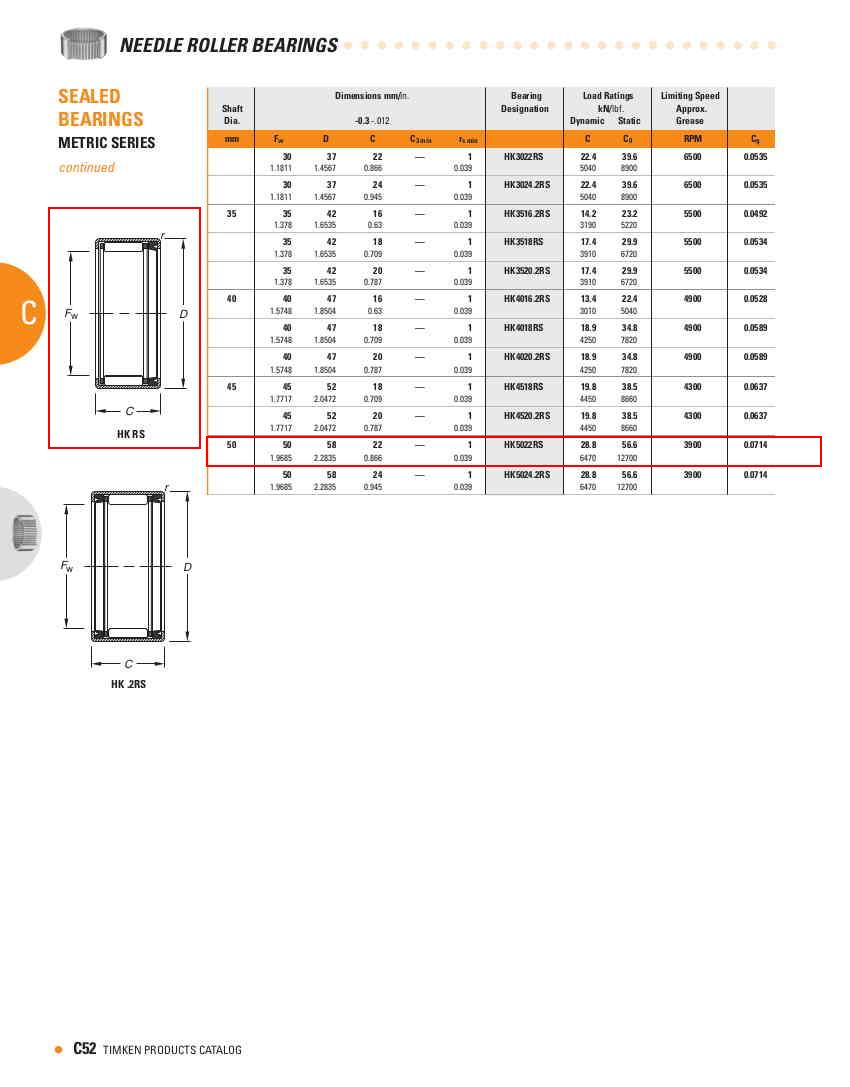
As it is now the small seal is in the drawn cup needle bearing. Look
closely.
The picture is reversed. It is running on a hardened and ground surface.
Shaft wear is unlikely.
The seal will fail long before the shaft is worn. If the seal fails
just replace the drawn cup needle bearing with the built in seal.
If you build the seal surface into prop flange you will need to machine
away a lot of expensive material. Then the seal surface will have to
be ground.
If you want a separate seal it is best to glue on a wear sleeve on the
prop shaft
behind the prop flange that can be slipped off when dissembling the gear
box. It can be hardened and ground and even chrome plated.
In that case specify a teflon seal. This also complicates the housing
of course.
Paul Lamar
The Rotary Engine News Letter. Powered by Linux.
ACRE NL web site.
http://www.rotaryeng.net
You Tube
http://tinyurl.com/beqqxas
Copyright 1998-2013 All world wide rights reserved.