Paul,
You have sent me several things in the past and I down loaded one of the
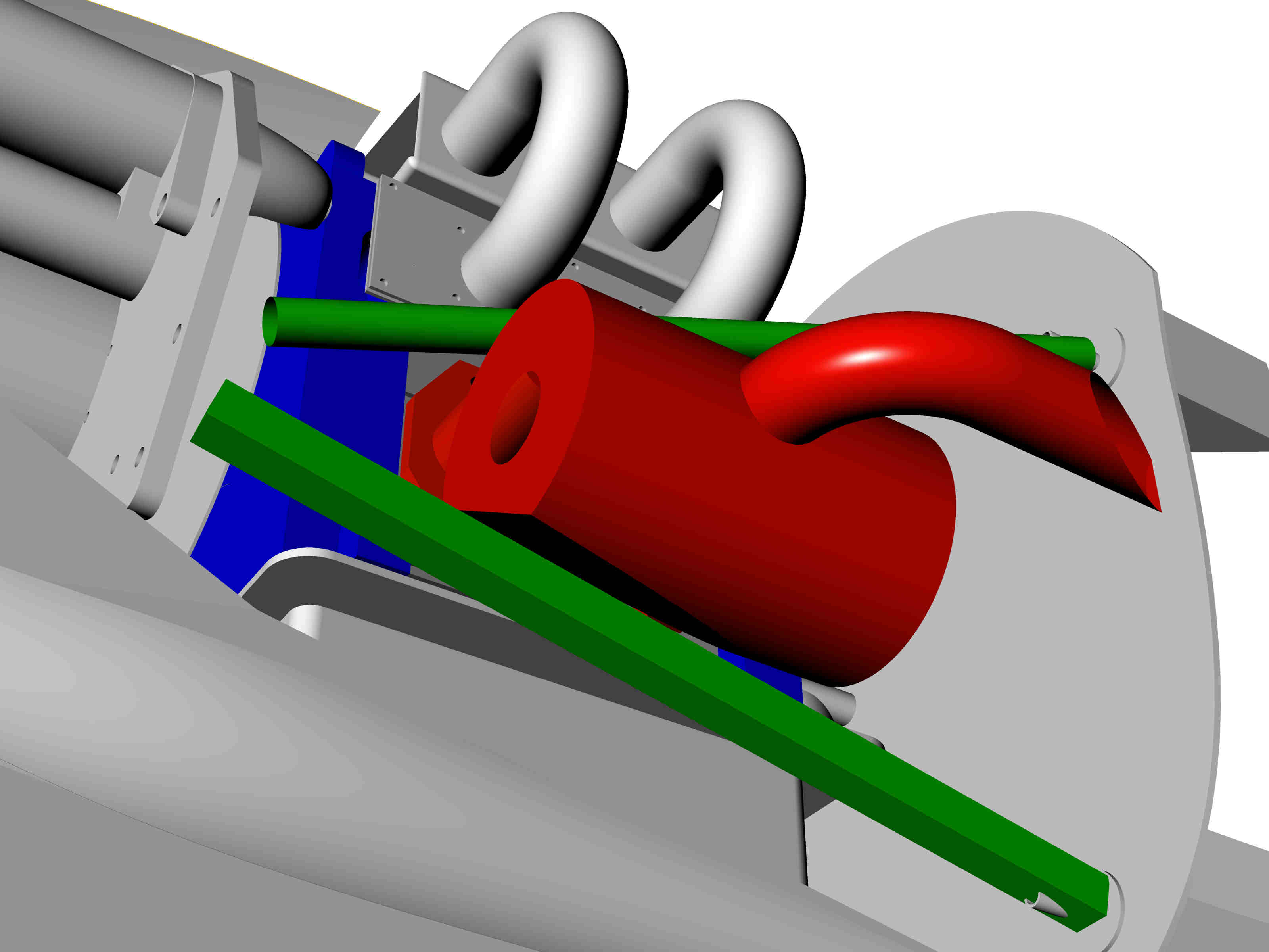
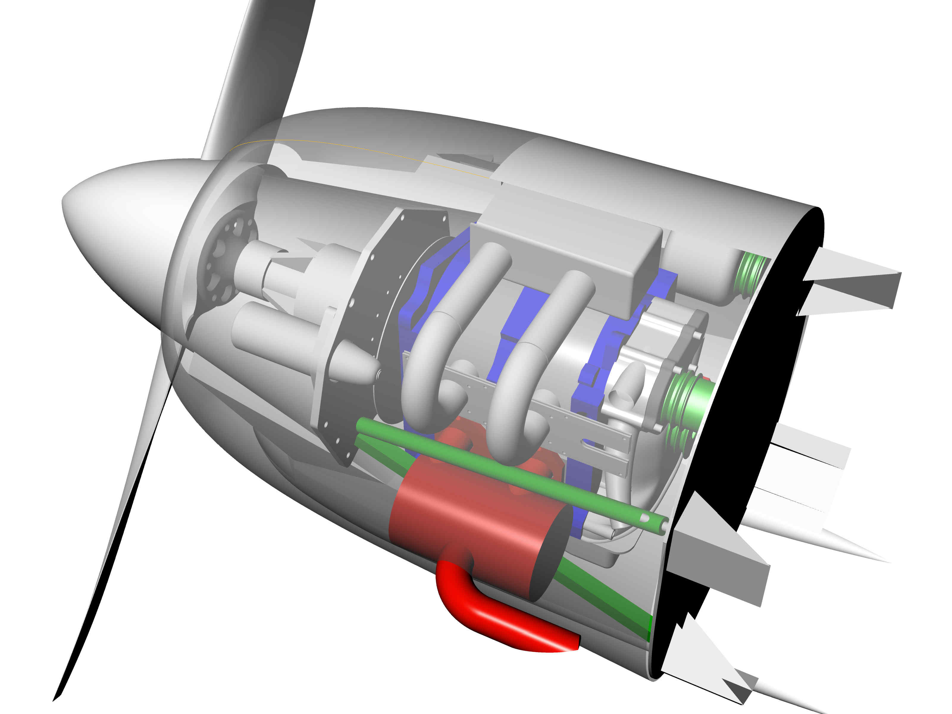
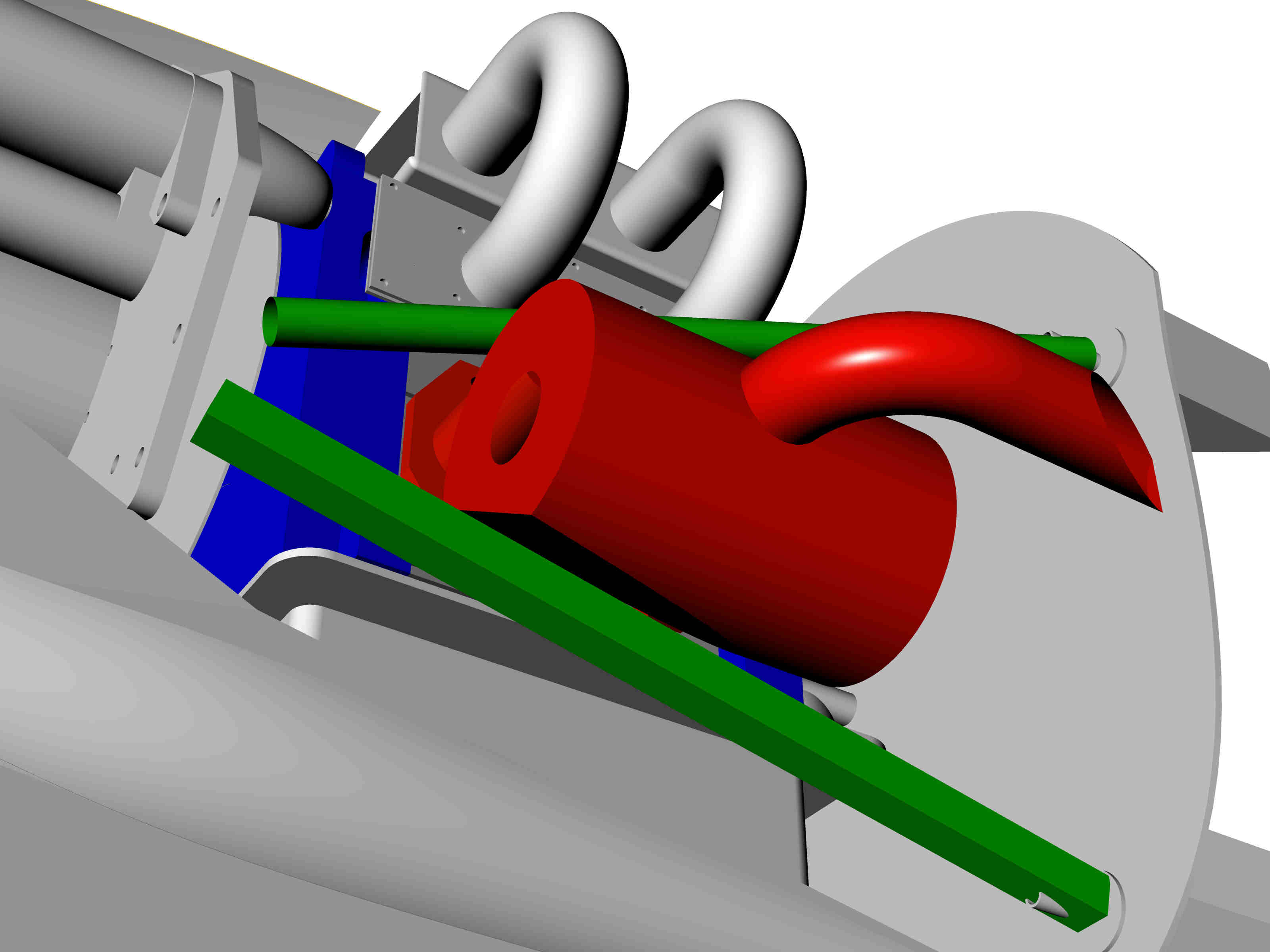
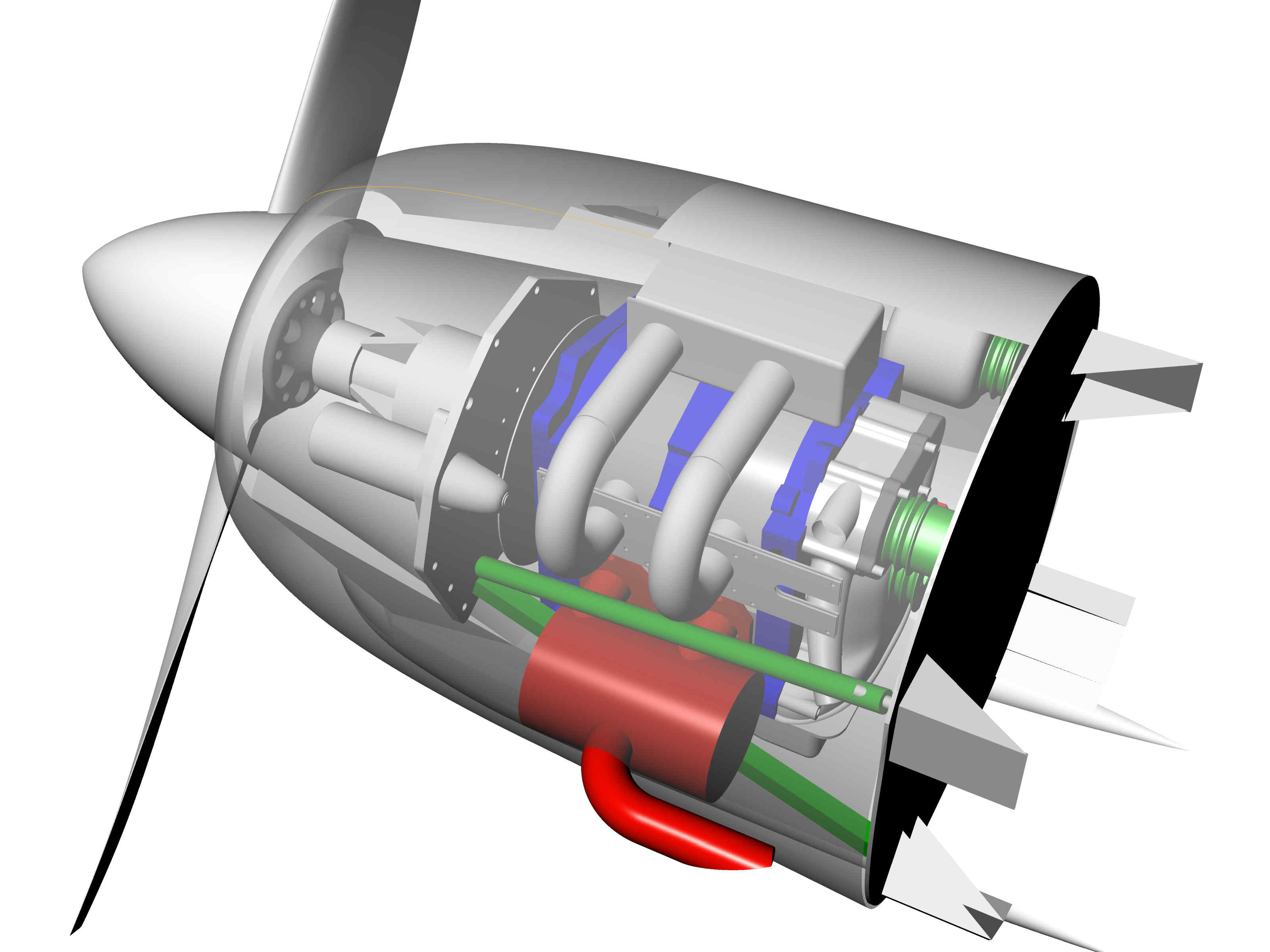
models from your site and this is what I have come up with so far(see
attached). It's pretty rough but I wanted to make sure i wasn't heading
down the wrong path before i got too far. Your comments and suggestion
are welcome.
This btw is for an aircraft I have designed and am currently building.
It's a small single seat sport plane. Kind of a mini fighter plane.
A few points of interest:
1. I plan on using your universal motor mount kit so the spools at the
firewall will be going away. If you could add those components(rod ends)
to the drawing I would appreciate it.
2. I obviously came up with my own adapter plate modified from the
Jeff's plate in the drawing I had along with the motor mount attach
points that I came up with by looking at the drawings you have been
doing of the Mike Collier LongEz. I rotated the starter 20 degrees
around the e-shaft from where it is located on the Jeffs plate. Not
sure if it is a sound design so your comments would be welcome.
3.Intake runners for the p-port. I just adapted the ones from the model
I downloaded slightly but don't know if the length is ideal or not.
There is plenty of room in the cowling to make them longer if need be.
4. Heat exchangers.
a. The oil cooler is on the side of the engine and i used the
dimensions for the stock Mazda oil cooler that Tracy mentioned in
his conversion manual.
b. The water heat exchanger mounted under the engine is a custom
size with 600 cubic inches of volume. It is a little less that
your model but I hope it is adequate.
5. The alternator and it's position came from your model. Obviously
there is significant conflict with the motor mount and oil cooler, but
there is plenty of space above the engine for it but I don't know how a
bracket could be made so if you do that would also be helpful.
6.Not drawn in yet are the induction intake and a few scat tubes that
will cool the alternator and the muffler. I'm guessing that is why
there is a tube in the middle of the muffler is for cooling. I also
plan on having some air passing through the cowling to carry away some
additional heat.
7. Thankfully there is still a lot of empty space in the cowling for all
the other stuff that will have to go in there.
Please let me know what you think.
Thanks,
Will Aldridge
Looks good. You will need longer intake pipes as this is tunned too high
for 2.85:1 GB. 18 to 20 inches
is about right. However if your GB is over 3:1 they are about right.
Paul Lamar
Also Will, I would suggest you do away with the internal muffler
as it will cause problems with the uni motor mount and will not be
quiet enough. Put an open on the bottom air cooled tunnel down the
center of the bottom of the aircraft and use a coax
muffler. The pilot can sit on the tunnel
with the rudder pedals on each side.
Paul Lamar
Paul,
This plane is very compact and believe me when I say there is no room
for a tunnel between the pilot's feet, and I have designed the load
paths in the plane so the bottom skin (foam/fiberglass sandwich) carries
the engine loads directly to the main spar and adding a tunnel would
compromise that. So I'm pretty much committed to the basic muffler
design shown.
As far as the motor mount goes, is the way I have the ends of the steel
tubes so far apart the problem or is it a heat issue or something else?
You mentioned runner length and the gearbox in your first reply. This
plane I think would be fine with 150 hp but I'm guessing I'll have north
of 200 with the setup I've drawn. I'm not concerned about getting more
power so if a 2.85:1 psru is more advisable then that's what I'll go
with. I also have a small fuel capacity so if the 3.17 gear box will
burn more fuel then I'm definitely interested in the lower ratio.
I know with the muffler I have drawn in I will cost me some power but as
I said I've got more than I need so that doesn't bother me.
Will
The fuselage is 27.5 inches wide so that is normal for a tandem cockpit.
My shoulders are only 20 inches across and I am not small.
Unless of course you are a really big guy :)
The tunnel only needs to be six inches wide and six inches tall.
I am sure the seat is at least six inches or taller as other wise the
pilot would
not be able to see out.
The tunnel will enhance the structural strength. It will decrease the
tendency to buckle.
I would also make it out of metal as you will need some metal down there
to protect
the composite from exhaust heat.
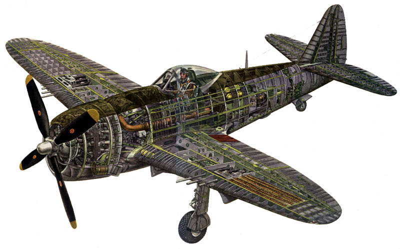
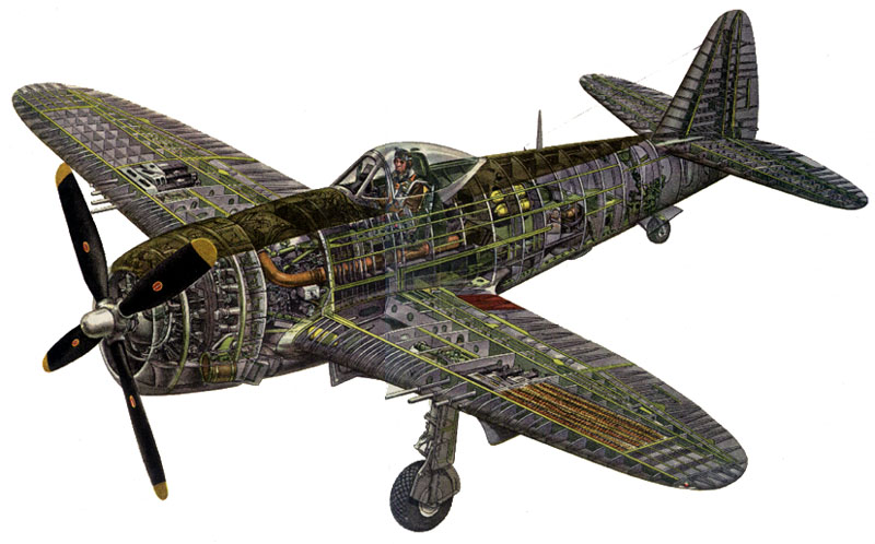
The P47 had a large tunnel for air ducting as the turbo charger was
in the aft fuselage.
It is not just power. The fuel burn (BSFC) is lower at the torque peak.
With 18 to 20 inch intakes the
torque peak is at 6,000 RPM. If you intend to cruise the airplane at a
lower RPM than
the intake runners should be even longer. That will reduce the top HP.
You have plenty of
room for longer runners.
The fuel burn is also a function of the back pressure
in the muffler.
The structural integrity of the universal mount depends on the tubes
converging to a point
in space close to the motor plate.
Apparently you are making a trade off for styling. That is something
they used to do in cars :)
Now all cars are beginning to look likethe Toyota Prius because that
has the lowest drag factor
and gives the lowest fuel burn. Of course that is your call. I just make
suggestions :)
I am glad that more people are starting to use Rhino. It enhances our
ability to share
ideas.
Paul Lamar
The Rotary Engine News Letter. Powered by Linux.
ACRE NL web site.
http://www.rotaryeng.net.
You Tube
http://tinyurl.com/beqqxas.
Copyright 1998-2014 All world wide rights reserved.