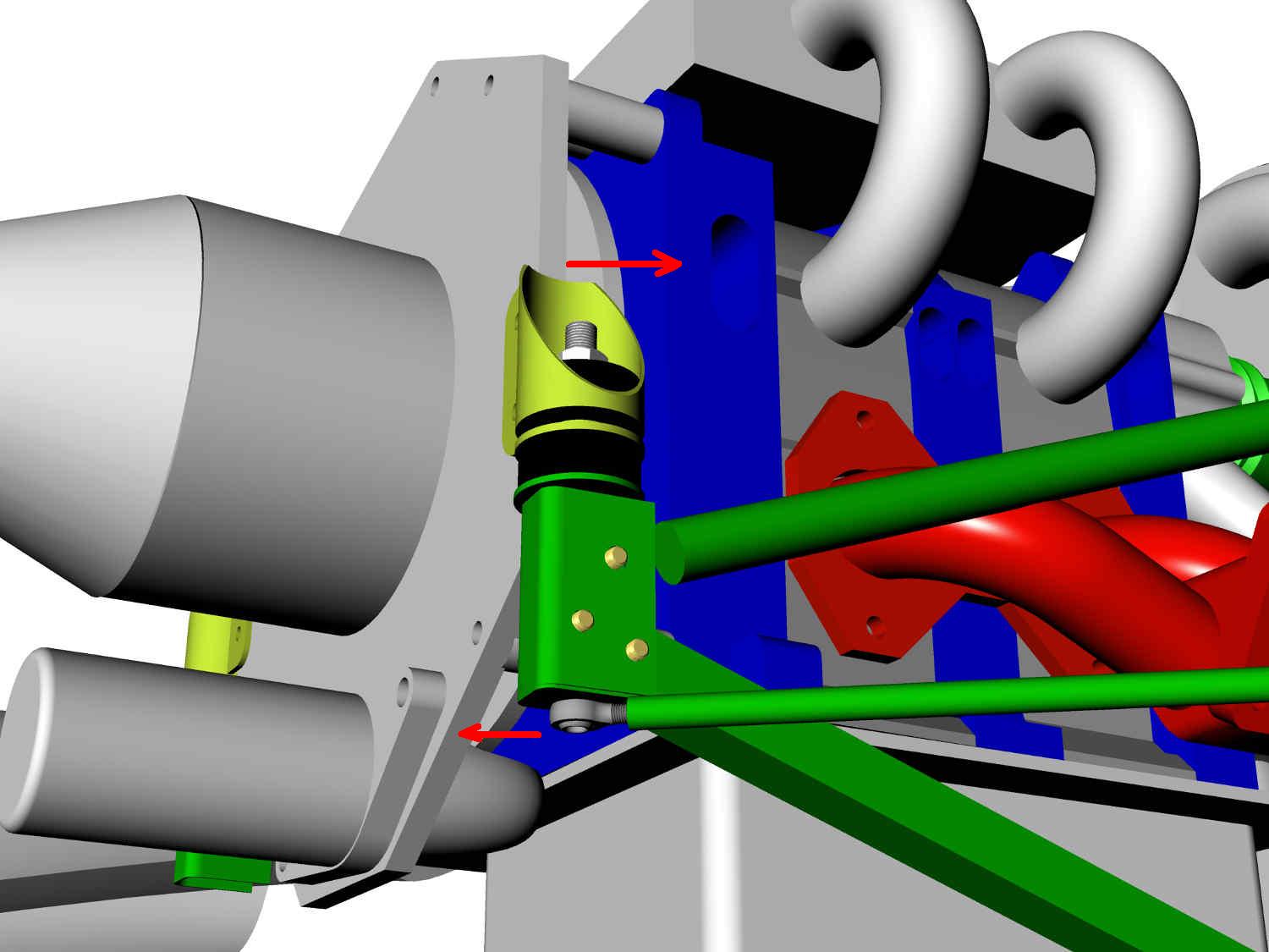
Richard, Here are some 3D's. The dims will be along shortly.
I got the motor plate. Mike Collier thanks you :)
I would make the lower 1 inch square tubes a bit longer and trim them
after setting up the engine. That is the time to drill the holes in
them and bolt them to the steel rubber bushing holders.
The diagonal hard points can be attached to the back of the spar with
a 2 by 2 by .063" thick steel bracket bonded with epoxy. Epoxy is
about 3000 psi so that is a bit over kill at 12,000 pounds max load.
There is no real load on these 1/2 inch diagonals 99% of the time.
Only in a stall where the pitch changes rapidly. Don't use aluminum
for these brackets as epoxy does not stick to it unless it is
treated.
They can also go to the bottom of the spar if you wish. In that case
you might need high angle rod ends.
Same thing applies to the rear motor mount bracket at the top of the
firewall. Normally this tube has only about 50 pounds of tensile load
due to the main rubber bushings located near the CG of the engine.
The down thrust angle can be adjusted to minimize trim drag from the
canard by adjusting the length of this tube. Standard practice in a
Questair Venter for best top speed.
Paul Lamar
Paul,
I would recommend to build statically determinate.
One of the 2 thinner bars can be missed.
Avoids assembly tensions and tensions due to temp differences during use.
Regards,
Henk van Ooijen
You are absolutely correct.
Your the first person in 16 years of the news letter to mention
"statically determinate" Henk.
I am impressed. I suspect you teach mechanical engineering at some
university some where. Am I right? Either that or you placed close attention
in statics class :)
This universal motor mount design is actually an invention. I did not
bother to
apply for a patent as it would never pay off. Too easy to copy and too hard
to defend. I build it first and then solve the inevitable problems later :)
The rubber joint compensates for a lot of sins. As some Brit engineer said
"An ounce of rubber is worth a pound of engineering."
Any conflicting deflections due to CTE differences cause very small
angular deflections in
the rubber bushing holder about a longitudinal axis deflecting the rubber.
The lateral loads are minimal. The reason I used two small tubes was a
belt and
suspenders approach. A half inch tube is great in tension but could buckle
in compression at this length. The job could be done with wires and turn
buckles.
WW I tech :)
One of the key points about this invention is the two bolts fastening the
rubber bushing to the lower square tube prevent the rubber bushing
holder from
rotating in the transverse axis. This would not be necessary if the
upper and lower
members were attached to the same point. A rather impractical solution.
I wish I had a four bar simulator or FEA to study this design. If you
have access
to such software I would love to see the results.
This is Mike Collier's Long EZ universal motor mount.
Paul Lamar
The Rotary Engine News Letter. Powered by Linux. ACRE NL web site.
http://www.rotaryeng.net You Tube
http://tinyurl.com/beqqxas
Copyright 1998-2014 All world wide rights reserved.